Modern aerospace components, complex automotive molds, and precision medical devices require advanced multi-axis manufacturing equipment. Industrial workshop managers frequently face a critical machine tool choice when upgrading their production floor capabilities. Should you invest in a true simultaneous multi-axis setup, or does a positional indexing configuration offer enough utility?
While both setups utilize a fourth rotational axis, they operate on completely different mechanical control principles. Choosing the incorrect setup can lead to slow cycle times, poor surface tracking, and visible cutter marks. This technical guide explains the structural differences between these setups to help you select the ideal 4-axis simultaneous machining center for your production lines.
1. Defining the Technical Architectures: Continuous Cut vs. Index Lock
The fundamental difference between these two systems comes down to how the CNC controller coordinates the rotational axis during a cutting pass.
 3+1 Positional: [Rotational Axis Moves] ──> [Axis Locks Rigidly]  ──> ❌ Step-by-Step Plane Milling
 4-Axis Continuous: [XYZ Linear Travels] ──═── [A/B/C Axis Rotates] ──> ♻️ Flawless Continuous Sculpting
3+1 Positional Indexing Machining
In a 3+1 positional configuration, the machine utilizes the fourth rotational axis solely as a component indexing indexer. The servo motor rotates the workpiece to a specific target angle, and a heavy-duty hydraulic brake locks the table rigidly. Once locked, the standard X, Y, and Z axes execute standard flat milling cuts. The rotational axis never moves while the cutting tool touches the metal.
True 4-Axis Simultaneous Machining
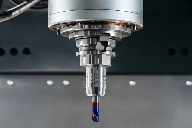
A true 4-axis simultaneous machining center keeps all four axes moving dynamically at the exact same time. The master CNC controller calculates linear movements along the X, Y, and Z paths while continuously rotating the work table. This continuous coordination allows the cutting tool tip to maintain a constant contact angle across sweeping, multi-directional curves.
2. Analyzing Surface Quality and Micro-Finish Accuracy
Academic metal-cutting research confirms that continuous multi-axis interpolation delivers vastly superior surface finishes compared to step-by-step indexing methods.
                  Cutter Contact Area Over Curved Faces:
   ┌──────────────────────────────────────────────────────────────────┐
   │ 3+1 Indexing: Leaves visible step marks at geometric boundaries. │
   ├──────────────────────────────────────────────────────────────────┤
   │ 4-Axis Continuous: Maintains a uniform tool path across profiles.│
   └──────────────────────────────────────────────────────────────────┘
When you use positional indexing to cut a curved profile, the tool must approximate the slope through multiple flat passes. This step-by-step approach leaves tiny, visible ridge lines and rough finish boundaries wherever the table indexes to a new position.
Conversely, continuous fourth-axis movement allows the cutter to sweep smoothly across the entire face of the metal workpiece. This fluid movement removes the need for secondary manual polishing or sanding routines, allowing your shop floor to achieve mirror-smooth finishes directly from the machine enclosure.
3. Strategic Selection Matrix: Part Geometries and Production Environments
Do not base your machine equipment purchases on upfront capital tool costs or superficial brand names alone. Instead, evaluate your specific workpiece geometries by walking through this clear engineering blueprint checklist:
Review Part Geometry ──> Check Secondary Facet Locations ──> Select the Optimal CNC Setup
-
The Multi-Faceted Part: Choose efficient 3+1 indexing if your parts feature holes and slots drilled onto different flat faces.
-
The Continuous Curve: Select a true 4-axis simultaneous machining center if you manufacture complex cams, propellers, or impellers.
-
The Helical Profiling Task: Deploy continuous multi-axis tools when cutting variable-pitch industrial worms, compressor screws, or large rotor slots.
-
The Multi-Axis Set Optimization: Use continuous motion systems to eliminate secondary manual part flips, boosting your daily shop efficiency.
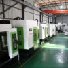
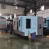
4. Maximizing Efficiency via Horizontal Machining Center (HMC) Architecture
Integrating a fourth axis into a horizontal machining center (HMC) layout unlocks massive productivity gains for industrial manufacturing networks.
 Traditional VMC:  [Single Part Fixture] ──> Manual Operator Rotation ──> ❌ High Labor Costs & Downtime
 Advanced HMC Set: [Rotational Tombstone] ──> Automated Multi-Face Milling ──> ♻️ Continuous Lights-Out Running
Standard vertical machines force operators to pause production frequently to flip parts manually inside the enclosure. In contrast, an HMC utilizes an integrated, high-torque rotary table that holds a multi-sided tombstone fixture securely.
This setup allows the machine to access four distinct faces of multiple workpieces in a single automated clamping cycle. By combining massive horizontal chip evacuation with continuous multi-axis movement, your factory can execute long, lights-out manufacturing shifts safely.
Conclusion: Future-Proof Your Manufacturing Infrastructure
Achieving elite manufacturing results requires utilizing high-performance CNC equipment that maintains strict tolerances under demanding production schedules.
Stop limiting your shop’s machining capacity with unoptimized three-axis layouts that require slow, manual part flips and leave rough finishes. Upgrading your production floor to our advanced 4-axis simultaneous machining center platforms ensures absolute geometric precision and rapid cycle times. We engineer every rotary table and linear guide rail to maximize your factory output and maintain ultra-tight tolerances over years of service.