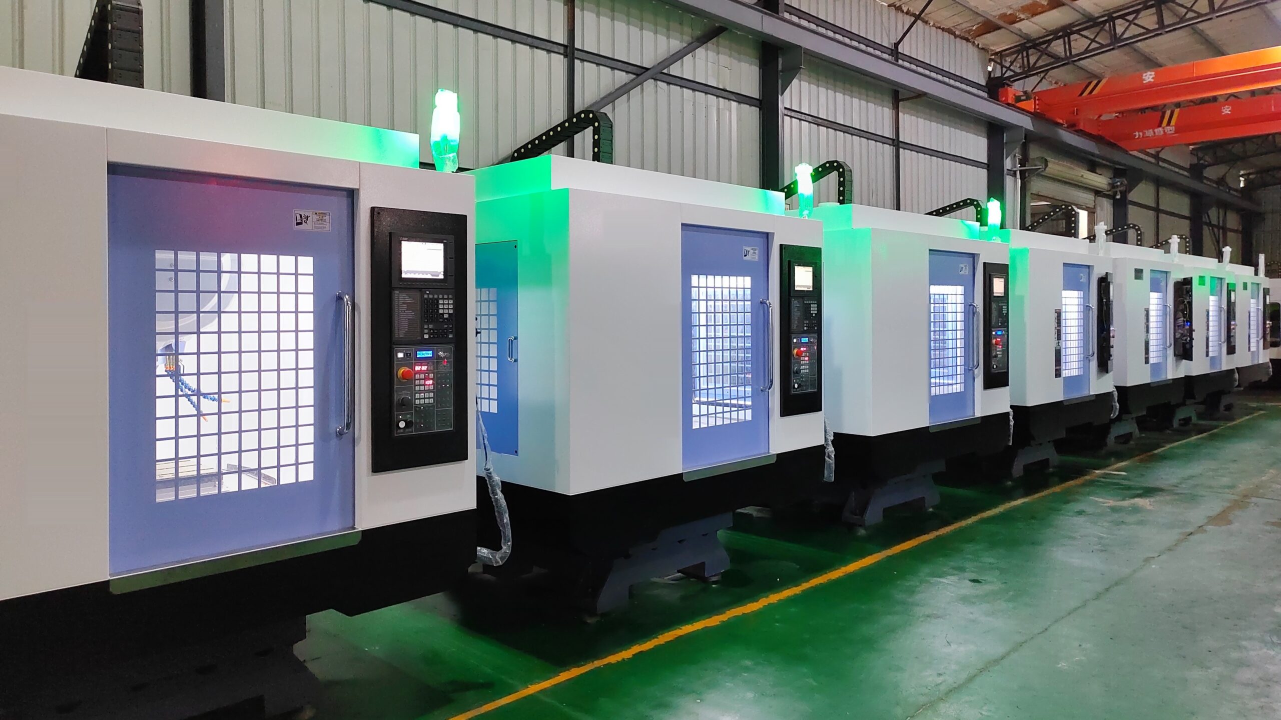
A small aluminum cover with thirty short holes spends a surprising share of its drill tap cycle time not cutting. The axes start and stop between holes. The spindle stops and restarts at each tool change and, in rigid tapping, reverses at the bottom of every tapped hole. And aluminum chips can still be sitting in a blind hole when the next tool comes down.
Each of these follows from how the machine moves. Once you see the mechanism, you know which figure on a spec sheet matters for your part and which one doesn't.
Where the drill tap cycle time goes
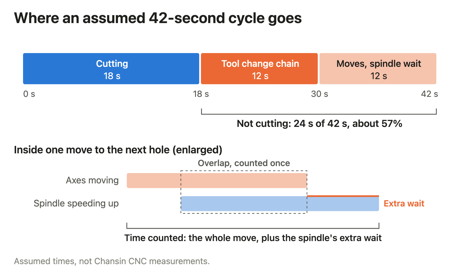
Time every machine between the same start and end points, for example from the part clamped and the cycle ready to the program end with the part ready to unload. Within that window, each second goes to whichever step is holding up the next operation.
| Assumed time per step | Short-hole part | Longer-cut part |
|---|---|---|
| Cutting | 18 s | 40 s |
| Tool change chain | 12 s | 12 s |
| Short moves and remaining spindle speed changes | 12 s | 12 s |
| Total | 42 s | 64 s |
Both columns use assumed times, not Chansin CNC measurements. In the first, 24 of the 42 seconds aren't cutting, about 57%. In the second, the same 24 seconds are 37.5% of a 64-second cycle. If both parts save the same seconds on moves and tool changes, that saving is a smaller share of the 64-second cycle.
Why short moves rarely reach full rapid speed
An axis can't jump to rapid speed. It accelerates at a limited rate, then has to slow down at the same rate before it stops. On a long move there's a stretch at full speed in between. On a short move the axis reaches the halfway point first. It has to start slowing down without ever reaching full speed.
Take a symmetric example, with the axis speeding up and slowing down at the same constant rate: an assumed acceleration of 10 m/s², about 1 g, and a rated rapid of 48 m/min, which is 0.8 m/s. The axis needs 32 mm to reach full speed and another 32 mm to stop. Any move under about 64 mm never gets there.
A 20 mm move then takes about 0.09 seconds. Dividing the distance by the rated speed gives 0.025 seconds, less than a third of that. Jerk limits, which smooth the start and end of each move, add to that; how much depends on the limit set in the control.
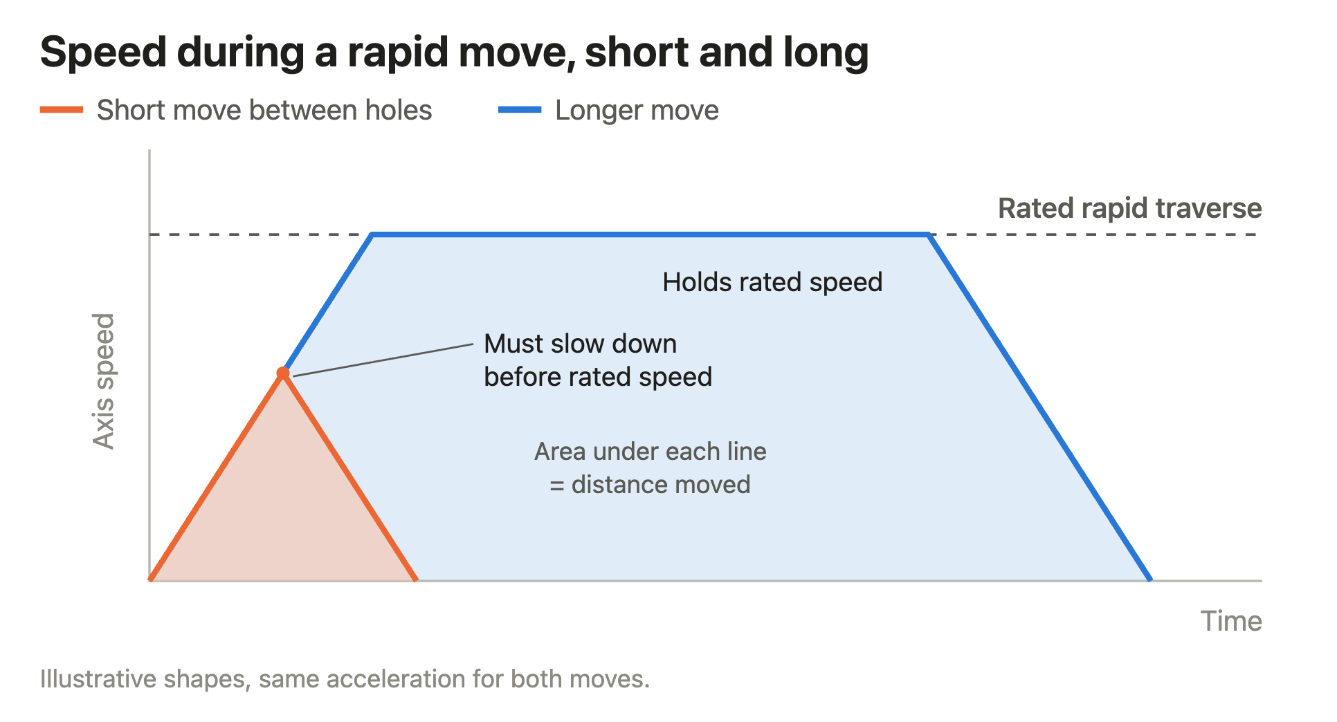
That's why the acceleration figure matters as much as the rapid traverse on a part with closely spaced holes. Time the real moves between holes, with the same tool length and clearance height on every machine you compare.
How tool changes count in drill tap cycle time
A tool change is a chain of steps. The spindle slows to a stop and orients, the tools are exchanged, and the spindle speeds up again to the next tool's speed. The axes usually move to and from the change position along the way.
Tool-to-tool time covers only the exchange. ISO 10791-9 times cut-to-cut changes on machining centers by repeating them against a reference position in the work area; the spindle need not rotate for the test, except to orient where needed.
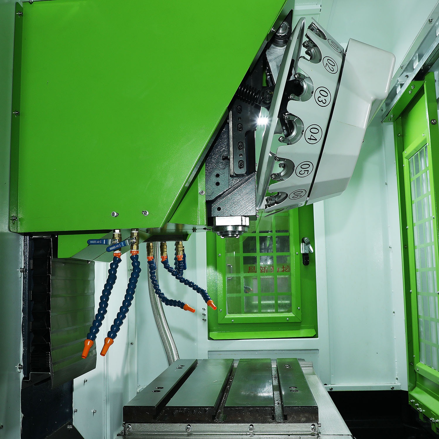
On your own part, the spindle stopping and getting back up to speed is part of the change. Time from the moment one tool stops cutting to the moment the next one starts, and ask the supplier which figure they quote and where it starts and ends. If tool preselection changes the result, test with your own tool order and magazine layout. Our tool magazine guide covers how the tool list affects that setup.
Rigid tapping adds a spindle stop inside every hole. The control synchronizes Z-axis travel with spindle rotation at the programmed thread lead. At the programmed depth, both slow to a stop, then reverse in sync to withdraw the tap. On a part with many tapped holes, that synchronized stop, reversal and withdrawal repeats in every hole, so its time adds up hole by hole. Time it in your own program rather than adding spindle and Z-axis times separately.
Count chip interruptions in drill tap cycle time
With some aluminum alloys, tools and feeds, chips come off long and can pack into a blind hole; chip evacuation is a known issue when drilling aluminum. A chip left in the hole has to be cleared before the next drill or tap arrives. That takes a coolant flush, an extra peck or a clearing move. Each extra peck adds a retract and a re-entry to the hole's cycle, so time the drilling cycle as your program actually runs it.
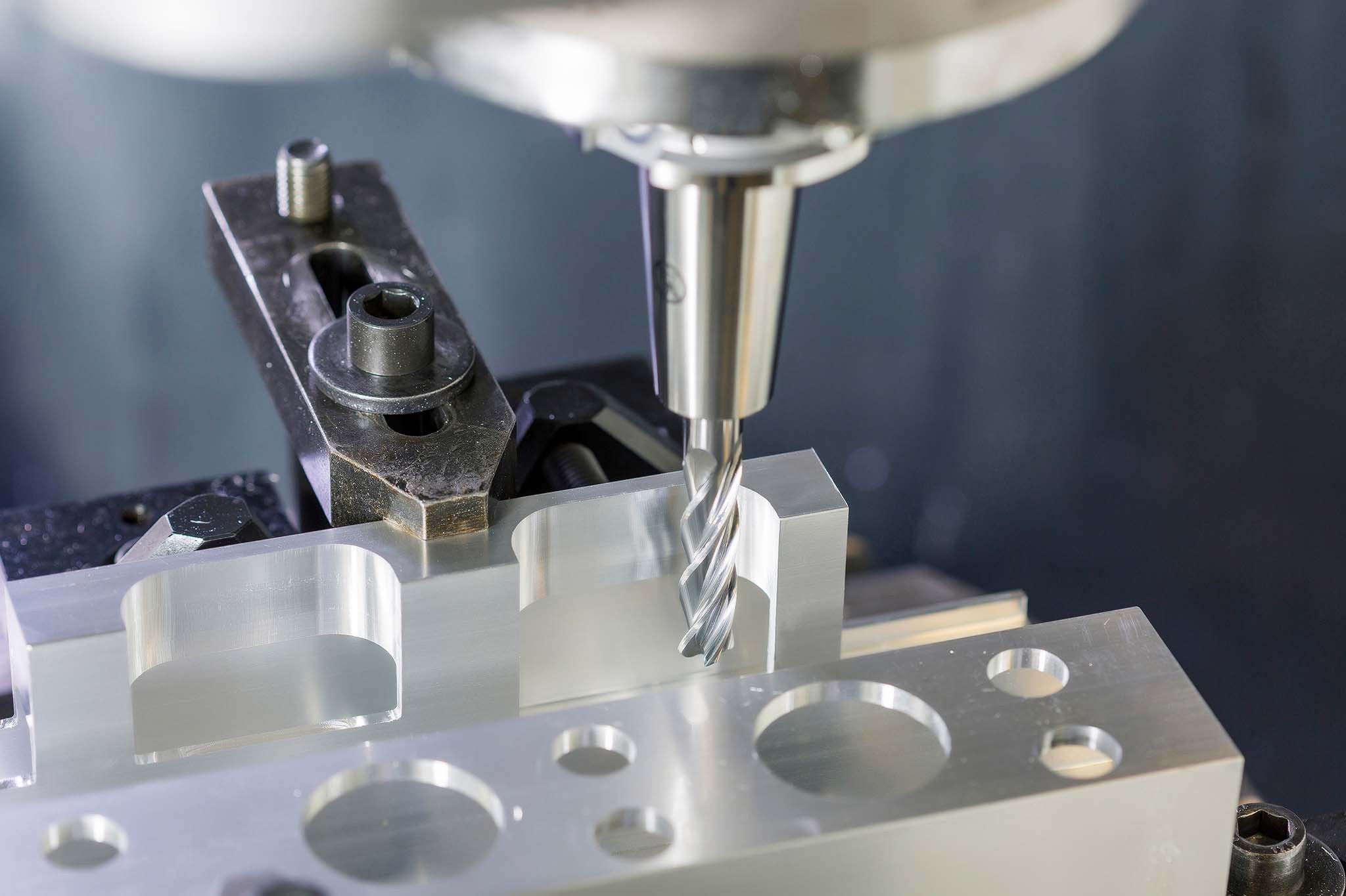
Watch several parts in a row, long enough for chips to build up, and record how often clearing interrupts the cycle. In one published case, a shop machining aluminum covers on BT30 machines switched to minimum quantity lubrication and had to plan chip removal and cleaning as part of that change.
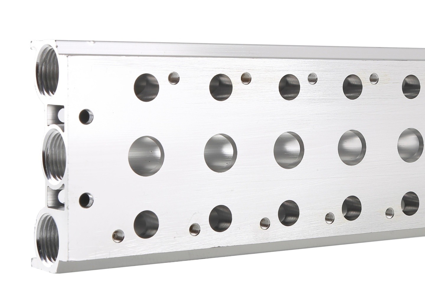
For parts with longer cuts, or where loading and chip clearing take most of the time, the vertical machining center you already have may do the job. Try changing the coolant direction and the chip route before you choose a new machine on a tool change figure measured with no cutting.
How we set up a drill-tap center for small aluminum parts
Our CS-T7, CS-T8, CS-T10, CS-T13, CS-T16, CS-T20 and CS-T25 drill-tap centers have a 20,000 rpm direct-coupled BT30 spindle, a 48 m/min rapid traverse on each linear axis and tool-to-tool changes from 0.8 seconds. The CS-T6 has a BT30 spindle at 20,000 rpm and the same rapid traverse.
For a part with many short holes, we look at your tool order and the distances between holes, then at where the coolant nozzles point and how chips leave the fixture.
If you have a program and a sample part, send them with the fixture and tool list through our inquiry form. We'll recommend a configuration and estimate the cycle time.
Sources
- ISO 10791-9:2001, test conditions for machining centers: evaluation of the operating times of tool change and pallet change
- Circular path tests on high-speed machine tools: acceleration limits on short paths
- MAPAL, aluminum cover machining on BT30 machines: switching to MQL, chip removal and cleaning
- Siemens, SINUMERIK ISO Milling Programming Manual (04.07), §4.1.11 rigid tapping cycle G84
- Sandvik Coromant, drilling tips and techniques for different materials: aluminum alloys
All times in the table, the 10 m/s² acceleration and the move lengths are illustrative, not Chansin CNC measurements.