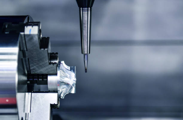
Aerospace procurement officers, precision manufacturing engineers, and defense tier-1 suppliers must look beyond basic catalog parameters when sourcing advanced production equipment. Achieving micron-level precision inside a climate-controlled laboratory is entirely different from maintaining it across consecutive manufacturing shifts. Specifically, high-value component buyers frequently raise a critical operational question: “A multi-axis machine tool lists a nominal ±0.005 mm machining accuracy specification, but does this precision drop during dynamic 5-axis simultaneous interpolation? Furthermore, how can we objectively verify these tolerances during aerospace part acceptance checks?”
Evaluating the complex kinematic chain and thermal variables of high-precision equipment reveals the true operational boundaries of your machine shop. Understanding the hardware mitigation strategies and formal validation protocols allows you to secure flawless production metrics for demanding projects. This technical guide outlines the essential machine features required to maintain micron-level tolerances and details the precise inspection methods used to audit finished components.
The Core Kinematic Challenge: Precision Retention in 5-Axis Simultaneous Machining
Maintaining a true ±0.005mm machining accuracy across a complex 3D toolpath introduces severe structural and thermodynamic challenges. During 5-axis simultaneous milling, geometry errors do not stem from a single linear guide rail. Instead, errors accumulate across multiple mechanical components, including linear axis positioning lag, rotary table indexing variations, tool center point (TCP) calculation delays, and structural thermal growth.
While a high-resolution rotary axis (0.001℃ indexing steps) provides the theoretical math needed for micron-level positioning, real-world friction and tool pivot-length errors can quickly degrade these tolerances. Ambient factory temperature shifts and heat generated by the high-speed spindle can easily cause machine castings to expand by dozens of microns. Without active hardware counter-measures, this thermal growth can destroy your tightest manufacturing tolerances.
The Hardware Blueprint: Advanced Systems That Secure Dynamic Accuracy
To overcome these structural deviations and prevent positional drifting, modern machining centers integrate three foundational hardware subsystems.
1. Full Closed-Loop Linear Scale Feedback Systems
Standard machines rely on rotary encoders attached to the drive motors to guess the position of the machine table. This open-loop approach fails to account for ball screw thermal expansion or physical backlash. Premium multi-axis platforms use high-resolution absolute glass scales mounted directly to every moving linear axis instead. This setup reads the exact physical location of the machine table in real time, allowing the CNC controller to instantly correct for screw stretch and keep positioning crisp.
2. Automated Probing and Kinematic Calibration Cycles
Thermal expansion changes the exact distance between the spindle nose and the physical center of rotation throughout the workday. To counteract this drift, advanced machining setups feature integrated touch probes and precision ceramic calibration spheres. The machine runs an automated macro routine every few hours to measure positional variations across the X, Y, and Z directions. The controller then updates its center-of-rotation compensation matrix automatically, neutralizing thermal drift before it can alter your workpiece dimensions.
3. Zero-Backlash Roller Gear Cam Driving Mechanisms
Traditional worm-gear rotary tables wear down over time, creating mechanical play (backlash) that ruins your surface finish during directional changes. High-spec turning axes utilize preloaded roller gear cam systems or direct-drive torque motors instead. This rigid driving method eliminates mechanical play, allowing the rotary C-axis to achieve an incredibly fine $0.0001^\circ$ indexing resolution that maintains its accuracy across years of continuous operation.
Three Proven Validation Methods for Procurement Inspections
Buying teams must never accept verbal quality guarantees or unverified factory calibration certificates. You must implement standardized, hands-on testing protocols to confirm that the equipment performs reliably under load.
Standardized Geometrical Workpiece Machining (ISO 10791 / NAS 979)
The most conclusive method to verify multi-axis capability involves cutting a standardized test geometry under full production conditions. Procurement inspectors typically require the factory to machine a cone-frustum specimen or an enterprise-grade NAS 979 S-shaped thin-wall piece. Reviewing the finished S-shape profile on a Coordinate Measuring Machine (CMM) reveals the exact dynamic synchronization errors of your machine, showing you how well the system coordinates complex curved movements.
Ballbar Circularity and Interpolation Diagnostic Testing
Before committing to raw material cutting, technicians can map the machine’s geometric pathing using a high-precision telescoping ballbar system. The machine executes a programmed circle path while the ballbar records minute variations down to the micron level. This test quickly catches stick-slip errors, scale mismatch issues, and reversal spikes at the axis quadrant crossover points, giving you a clear picture of the machine’s mechanical alignment.
Accompanying Furnace Sample Material Verification
For critical aerospace or defense components, inspectors use an accompanying sample validation strategy. Machinists mount a certified, standardized check block directly alongside the main workpiece raw stock inside the machining enclosure. The spindle mills the check blocks using identical feed rates and tool change cycles. Measuring this control sample on a high-end CMM provides a verified record of the machine’s accuracy during that specific manufacturing run.
Conclusion: Secure Your Ultra-Precision Sourcing Infrastructure
In conclusion, consistently maintaining a true ±0.005mm machining accuracy requires a rigid machine design that combines closed-loop glass scales, zero-backlash rotary drives, and automated calibration probing.
Stop risking your critical aerospace contracts, material budgets, and component quality on low-tier milling machines that warp under load and lose their precision during multi-axis movements. Upgrading your shop floor to a certified, fully reinforced CNC machining platform guarantees absolute geometric stability, predictable surface finishes, and repeatable tolerances across every manufacturing shift. We build every structural casting and configure every closed-loop control system to satisfy the highest international quality standards.
Contact our precision manufacturing applications group today to schedule a live NAS 979 S-shape cutting demonstration and secure a detailed machine configuration quote.