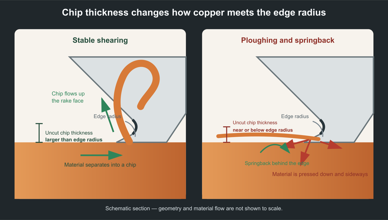
Pure copper smears and forms heavy burrs because it is highly ductile and readily adheres to the cutting edge. When the edge is dull, the effective chip thickness is too small or chips cannot leave the cut, the tool pushes and ploughs the material instead of shearing it cleanly. Copper then builds up on the edge, changes the tool’s effective geometry, drags across the new surface and bends at unsupported exits.
The first response should not be a universal speed-and-feed change. Confirm that the material is actually a high-purity copper grade, inspect the cutting edge, check whether the tool is making a real chip, and give that chip a clear path out. Pure copper, brass and other copper alloys can behave very differently even though they look similar on a material list.
Pure copper is not difficult because it is hard
Pure copper is soft compared with many steels, but softness does not guarantee easy chip formation. The Copper Development Association and German Copper Institute describe pure copper as difficult to machine because of its high ductility and cold-workability. It tends to produce long chips, substantial chip compression and built-up edge. These behaviours increase mechanical load at the edge and can degrade the machined surface.
Brass often machines more freely because its composition and microstructure help chips break. Other copper alloys may contain elements or phases that change adhesion, strength and chip formation. A process that works on a free-cutting brass should not be transferred to C101, C110 or oxygen-free copper by colour or generic material family alone.
Smearing begins when cutting turns into ploughing
A sharp edge with enough undeformed chip thickness shears material and sends it up the flute. If the edge radius is large relative to the chip thickness, the tool may compress and push the surface before a chip forms. Part of the material flows sideways or springs back behind the edge. In micro-milling this size effect is especially important, but the same principle helps explain why a light “finishing” feed with a worn edge can make a conventional copper surface look wiped rather than cut.
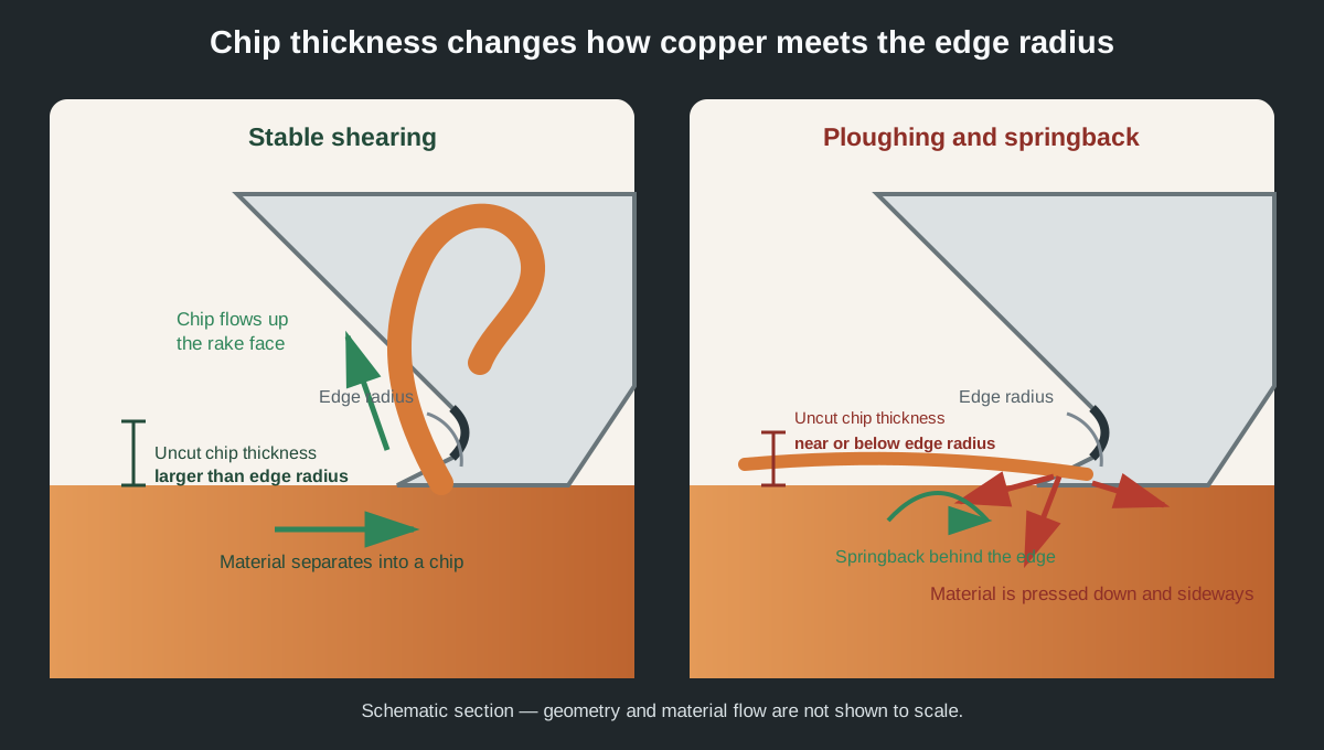
Reducing feed is therefore not always a safe cure for a poor finish. A lighter feed may reduce force, but it can also move the process closer to rubbing. The correct change depends on tool diameter, edge preparation, radial engagement, material condition and the tool manufacturer’s cutting data. Change one variable at a time and inspect the chip and edge after each trial.
Built-up edge changes the tool while it is cutting
Built-up edge is work material that adheres around the cutting edge and rake face. It creates an irregular temporary edge. As the deposit grows and breaks away, it can be carried with the chip or pressed into the work surface. This can produce a cycle of acceptable finish, sudden smearing, size change and renewed cutting even though the programmed path has not changed.
The DKI machining monograph explains that built-up-edge formation in copper depends on cutting speed, chip thickness and rake angle. It also notes that the appropriate response can differ by operation: increasing speed, chip thickness or rake may move a process away from one BUE region, while operations such as reaming or tapping may require a different low-speed, well-lubricated strategy. This is why one internet parameter table cannot diagnose every copper job.
Read the defect before changing the program
| What you see | Likely mechanism to check | First evidence to collect |
|---|---|---|
| Copper welded to a flute | Adhesion, heat, rough flute surface or poor lubrication | Edge and flute inspection before cleaning the tool |
| Shiny smeared floor or wall | Rubbing, ploughing or a changing built-up edge | Actual chip thickness, edge sharpness and finish progression through the cut |
| Long ribbons around the cutter | Ductile continuous-chip formation and inadequate evacuation space | Chip shape, radial engagement and flute loading |
| Scratches after the edge has passed | Chip recutting or a chip trapped between tool and surface | Coolant/air direction and chip accumulation in the pocket |
| Large exit burr on one edge | Unsupported ductile material bending ahead of the exiting edge | Tool exit direction, local support and edge condition |
| Size drifts while the surface changes | BUE growth/break-off, wear or thermal change | Part sequence, edge images and size trend rather than one final measurement |
The table is a diagnostic starting point, not a one-to-one fault code. More than one mechanism can be present. For example, a dull edge can increase ploughing, promote adhesion and make chip evacuation worse at the same time.
Correct the process in an order that preserves the evidence
Confirm the copper grade and condition
Separate pure copper from brass, bronze and free-machining copper alloys. Material temper, prior cold work and actual hardness can also change the cut. If the stock identity is uncertain, tuning the program around the wrong material model may only hide the problem temporarily.
Inspect the edge before changing multiple parameters
Look for adhered copper, edge rounding, chipping and uneven flute loading. Clean or replace a loaded tool before judging a new parameter. A polished, sharp, positive-rake geometry is commonly used for non-ferrous materials because it reduces friction and gives the ductile chip a smoother path, but the exact geometry and coating must be selected for the actual copper grade and operation.
Restore a real chip without overloading the tool
Check programmed feed per tooth against radial engagement, tool diameter and the cutter manufacturer’s data. If the tool is rubbing, a smaller feed may intensify smearing. If the edge is already overloaded, increasing feed can cause immediate failure. Use chip shape, spindle behaviour and edge condition to decide which side of that problem you are on.
Open the cut and clear the chip
A buried cutter has little flute volume available for long ductile chips. Reducing radial engagement or using a toolpath with more consistent engagement can create room for evacuation. Coolant or air should carry chips away from the finished surface, not push them into a closed corner. Lubrication matters for adhesion; flushing matters for recutting. They are related but not interchangeable jobs.
Control how the tool leaves the material
Exit burrs form where the remaining material loses support and bends before it separates. Check the exit direction, toolpath, local wall support and whether a finishing or chamfering pass reaches the edge without pushing a larger lip ahead of it. A deburring step can remove the symptom, but it should not be allowed to hide a worn tool or an unstable exit condition.
Functional surfaces need more than a roughness number
A copper part may meet size and still fail in use because a contact surface is smeared, an edge burr interferes with assembly, or recut chips have scratched a sealing or thermal interface. Pure copper can also deform during aggressive manual deburring. Inspection should therefore follow the feature’s function: edge condition, contact area, flatness, cleanliness and local surface damage may matter alongside diameter and roughness. If the part will be joined into a cold plate, joining distortion, datum transfer and leak testing become a separate downstream control problem.
A 2020 study of commercially pure copper micro-milling found a relationship between tool wear, surface roughness and burr characteristics under its specific 200-micrometre-tool test conditions. The numerical results should not be transferred to a conventional cutter, but the production lesson is useful: surface and burr trends should be tracked with tool condition, not inspected as unrelated defects.
When this diagnosis does not apply
If the material is an easy-machining brass or another alloy designed to break chips, pure-copper guidance may be misleading. If a burr appears only at a thin unsupported wall or a specific tool exit, geometry and support may dominate the result. If every flute shows similar damage and vibration marks appear throughout the cut, rigidity or chatter may be the primary problem rather than adhesion.
The test is simple: change one suspected cause, preserve the old tool and chips, and see whether the defect and its evidence move together. If they do not, return to the material, toolpath and workholding instead of continuing to tune speed and feed around an unproven diagnosis.
Three common misreads of a copper-milling problem
- Lower the feed first. If the edge is already rubbing, a smaller chip thickness can intensify ploughing and smearing.
- Change the coating first. Coating choice cannot correct a rounded edge, unsuitable chip thickness or trapped chips, and it still has to match the copper grade and operation.
- Add more coolant first. Lubrication may reduce adhesion, but chip recutting remains if the flow pushes long chips into a closed corner instead of clearing them.
Start with the defect, then inspect the material, edge and chip. A stable process keeps the edge shearing cleanly and protects the surface or edge that performs the part’s electrical, thermal or assembly function.
Sources and Method
- Copper Development Association / German Copper Institute, “Recommended Machining Parameters for Copper and Copper Alloys” — industry technical guidance on pure-copper machinability, chip formation, built-up edge, tool geometry and cutting fluids.
- “On the Correlation Between Surface Quality and Tool Wear in Micro-Milling of Pure Copper,” Journal of Manufacturing Processes, 2020 — experimental evidence under defined micro-milling conditions.
- “Physical Modelling with Experimental Validation of High-Ductility Metal Cutting Chip Formation Illustrated by Copper Machining,” 2022 — modelling and experimental evidence on copper chip deformation and burr formation.
The symptom table connects published copper-cutting mechanisms with observable shop-floor evidence. Cutting parameters still have to be selected for the actual grade, tool geometry, engagement and machine conditions.