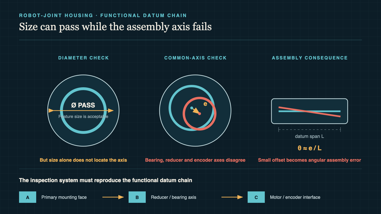
Answer first: A robot joint housing can pass every individual bore-size check and still create assembly error because diameter is not the same as axis location. The housing must preserve the relationship among the bearing or reducer axis, mounting face, encoder or motor interface and bolt pattern. The reliable method is to define one functional datum chain, control every setup transfer against it, and make the machining and inspection coordinate systems demonstrably equivalent.
This article studies one problem: why do individually acceptable features sometimes become an unacceptable robot-joint assembly? It does not assume a reducer type, bearing fit, material, tolerance or coating. Those are drawing- and assembly-specific.
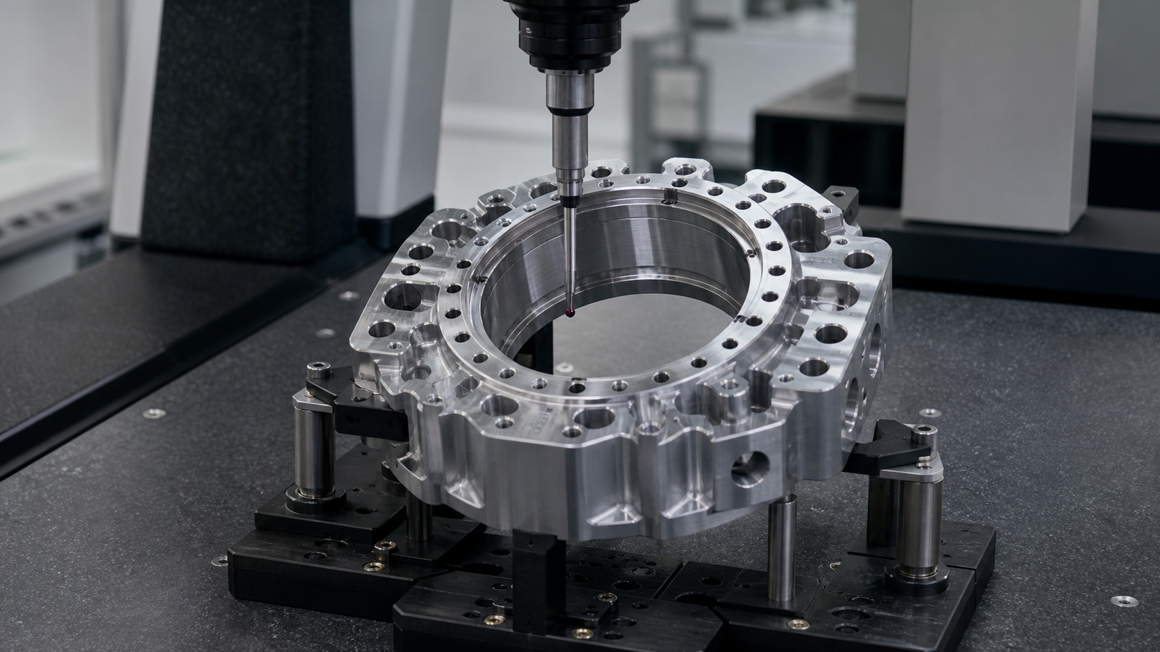
Diameter acceptance does not establish a common axis
A bore-size result answers whether the sampled diameter lies within its size specification. It does not by itself establish roundness, cylindricity, orientation to a mounting face, or location relative to another bore. ISO 1101 provides the symbol language for form, orientation, location and run-out controls; the drawing must use the control that represents the intended function.
For a joint housing, four error families should be kept separate:
- Size error: the bore is too large or small for the intended fit.
- Form error: the bore is not sufficiently round or cylindrical.
- Orientation error: the bore axis is tilted relative to the mounting face or another datum.
- Location error: the axis or bolt pattern is displaced relative to the functional datum system.
Two bores can both have acceptable diameters while their axes are offset or tilted. A reducer or bearing assembly then has to absorb the mismatch through clearance, preload, elastic deformation or forced alignment. The machine may have produced two “good diameters,” but the housing has not produced one coherent rotational system.
A small offset can become an angular error
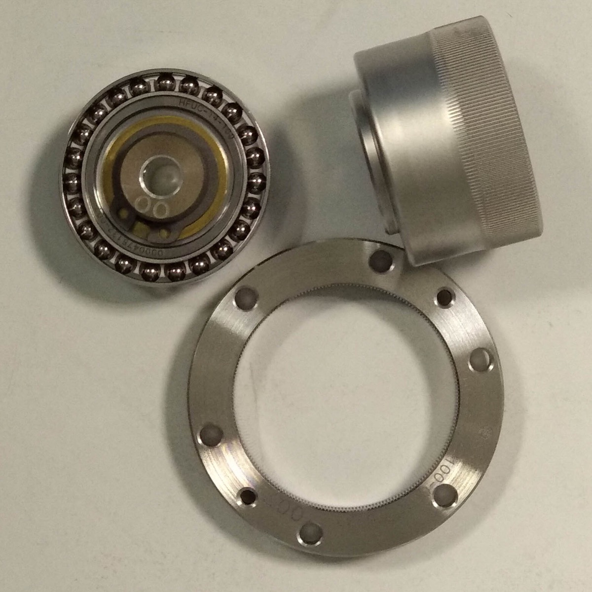
Consider a hypothetical joint housing with two fitted axis sections separated by an axial distance L. If their fitted centers differ by a radial amount Δr, the small-angle approximation is:
θ ≈ Δr / L
If Δr is 0.012 mm across 60 mm, θ is approximately 0.0002 rad, or about 0.011° (roughly 41 arcseconds). These numbers are an illustration, not a recommended tolerance. They show why a center displacement that appears small on a dimensional report can matter when it becomes an angular relationship across an assembly.
The same logic applies to a mounting face. A bore axis that is locally acceptable but tilted to the face changes the reducer or bearing seating relationship. The correct acceptance zone must therefore be specified on the drawing and evaluated from the defined datum, not inferred from a familiar fit class.
Where datum transfer creates hidden error
A datum transfer occurs whenever the part is relocated, flipped, removed for stress relief or finishing, or measured in a coordinate system reconstructed from different features. The transfer error is not only machine positioning error. It can include locator contamination, clamping deformation, probe qualification, thermal condition, feature-fitting method and the difference between the process datum and the drawing datum.
| Transfer | Hidden assumption | Evidence needed |
|---|---|---|
| Roughing fixture to finishing fixture | The semi-finished locator still represents the functional datum | Stock map, locator repeatability and released-part checks |
| Side A to side B | The second setup recreates the first axis | Common reference features, probing strategy and correlation part |
| Machining to CMM inspection | Both systems construct the same datum and fitted feature | Aligned datum definition, fitting rules, sampling plan and uncertainty review |
| Before to after coating | The functional fit and datum are unchanged | Masking or stock policy plus final-state measurement |
Reducing the number of setups can reduce transfer opportunities, but “one setup” is not proof of capability. Tool deflection, thermal drift, rotary-axis geometry, access, thin-wall release and probe uncertainty still remain. The correct question is not how many setups were used, but whether the final feature relationships are statistically stable and traceable to the functional datum.
Correlate the machine and inspection systems before blaming either
Coordinate measurement is not an absolute truth machine. NIST’s work on CMM uncertainty identifies contributions from machine geometry, probing, dynamics, thermal compensation and the measurement task itself. For a joint housing, disagreement often begins with different feature-construction choices: one system may fit a cylinder from many points over its full length while another samples a short section or uses a different filtering and datum-alignment method.
A correlation study should use the same stable part and document:
- part temperature and stabilization time;
- the exact datum precedence and any datum targets;
- probe/stylus configuration and qualification;
- the number, distribution and excluded measurement points;
- the fitting algorithm and any filtering;
- repeat measurements after removing and reloading the part;
- measurement uncertainty relative to the drawing tolerance.
If repeated measurements agree without reloading but diverge after reloading, fixturing or datum reconstruction is implicated. If both systems repeat well but disagree by a stable offset, their coordinate construction or compensation should be compared. If neither repeats, no useful machining correction can be calculated yet.
Use an error budget, but do not add every number blindly
For an early process review, represent the total relationship error as contributions from machining, setup transfer, part distortion, finishing and measurement. A conservative worst-case bound adds magnitudes. A root-sum-square estimate may be useful only when the terms are independent, random and supported by data. Systematic datum shift must not be hidden inside a statistical root-sum-square calculation.
The error budget is a diagnostic model, not the acceptance rule. The drawing’s geometrical specification remains the acceptance rule. The model helps identify which contribution consumes the margin and which experiment should be run next.
A practical failure investigation
Suppose the bores pass size inspection, but reducer installation requires uneven force and assembled runout is unstable. A disciplined sequence is:
- Confirm the assembly parts, preload, fasteners and installation method.
- Measure the housing’s bore form, axis location and orientation from the drawing datum—not only diameters.
- Repeat the measurement after unloading and reloading to expose datum reconstruction error.
- Correlate the CMM result with the machining probe or an independent calibrated method.
- Separate pre- and post-finishing states if coating or heat treatment is present.
- Only then change stock, toolpath, fixture or finishing compensation.
Research on high-precision robot reducers consistently treats transmission performance as the combined result of component manufacture, assembly and measurement. That does not prove a specific housing tolerance, but it supports the broader conclusion that interface relationships cannot be reduced to one bore dimension.
Engineering conclusion and limits
A joint housing is successful when its functional interfaces create the intended assembled axis. The minimum evidence is a drawing-defined datum system, a documented setup-transfer strategy, final-state geometry results and a measurement-correlation study whose uncertainty is appropriate for the tolerance.
This article cannot determine the correct bore fit, coaxial relationship, perpendicularity, surface finish or inspection frequency without the actual reducer, bearing, encoder, material, finishing process and assembly load. Those are design decisions, not generic machining facts.
Sources and method
The geometrical-specification framework follows ISO 1101:2017. Measurement-system cautions are grounded in the NIST report on CMM measurement uncertainty. The connection between component manufacture, assembly and robot-reducer performance is supported by the peer-reviewed review of high-precision reducer performance testing. The angular example and investigation sequence are original engineering illustrations; no source-specific tolerance has been transferred to a robot joint housing.