A quality engineer had to check the concentricity of two bores on one part: a 47 mm bore as the datum and a 118 mm bore held to it, with a tolerance of 0.02 mm.
His CMM said 0.032. The customer’s CMM said 0.024. A ZEISS inspection service measured it at 0.014. Same part, three answers, and the part both passed and failed depending on who measured it.
If you machine robot joint housings, you’ve probably met the same trap. Each bore checks fine on its own, but the reducer has to sit on one axis through both.
When both bores pass and the axis fails, check three things in this order: how the axis was measured, how the part was moved between the two bores, and how it was clamped. The fix that lasts is to bore both ends without unclamping the part.
What the reducer asks of the housing
Reducer makers publish these numbers. Harmonic Drive’s catalog for its CSF and CSG component sets takes the housing bore that holds the circular spline, toleranced H7, as datum A, and holds most of the other features to it.
For a size 25 unit, the shaft on the flexspline side has to be concentric to datum A within ø0.022 mm, and the mounting face of the circular spline square to it within 0.014 mm.
On a robot joint, those features are often at different ends or depths of the housing. Nabtesco’s design notes for its RH-N gearboxes make the same point without the numbers: watch the concentricity, parallelism and flatness of the mounting surfaces. Either way, it’s the relationship between the two ends that counts, not either bore alone.
1. Check the measurement first
In the ZEISS forum case, the reply that stuck was about the datum. The 47 mm datum bore was only 17 mm deep. An axis built from a short bore can tilt a little, and that tilt grows with distance.
If the datum axis is off by 2 µm across 17 mm, it’s off by about 12 µm 100 mm away. A ø0.022 mm concentricity only lets the axis sit 0.011 mm off centre, so that alone uses up the tolerance before your machine has made any error at all.
So before you touch the program, agree on the measuring method: datum bore scanned as a full cylinder, enough points on the second bore, the same strategy on your CMM and the customer’s. Then reload the part and measure again. If the number moves when the part is reloaded, the measurement or the way the part is held is part of the problem, and that needs fixing before you change the machining.
2. Check the flip
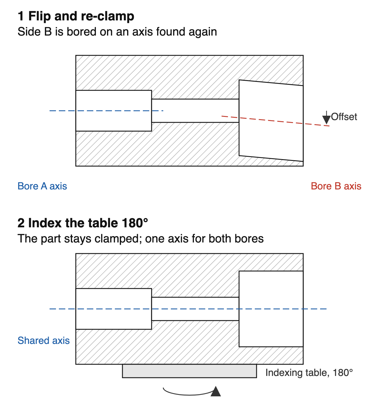
If you bore one end, then flip and re-clamp the housing for the other end, the second bore is cut on an axis the machine has to find again, from a fixture, an edge or a probe pick-up. Any error in finding it goes straight into the offset and tilt between the two bores.
Turning the part on a table won’t save you if the table can’t find 180° exactly. One machinist boring both ends of a pipe on a horizontal borer found the table crank “near impossible” to set to a true 180°, and was getting about 0.30 mm of runout after turning it.
Clamping adds its own error. A thin-walled housing clamped hard can be bored round and then spring out of round when it’s released, so clamp as lightly as the cut allows and on solid sections.
The fix that lasts: bore both ends in one setup
If the part never comes off the table, the second bore isn’t located from an axis found again. What’s left is the table’s indexing error, and how well the program knows where the table’s centre of rotation is. Both can be measured and set once, rather than found again on every part.
Rotary-table maker TJR lists its Hirth-coupling index tables, such as the HI-320R and the horizontal HHI series, at ±5 arc seconds indexing accuracy and ±1 arc second repeatability, in 1° steps. Its HR-255R worm-gear rotary table, which turns in 0.001° steps, lists 15 and 6 arc seconds.
An angular error at 180° tilts the second bore’s axis by the same angle. Over 100 mm between bores, 5 arc seconds is about 0.002 mm and 15 arc seconds about 0.007 mm. Both are inside the 0.011 mm a ø0.022 mm concentricity allows, and nowhere near the 0.30 mm of a hand-set table.
For a job that only needs 0° and 180°, the 1° Hirth-coupling table is the more accurate choice.
Two more habits help. Where both bores are the same size and you can reach them from one side, bore straight through in one pass with a long bar, so there’s no second axis at all. And if you have a workpiece probe, use it to check where the table’s centre of rotation really is before you rely on it.
Our comparison of reaming and boring covers why the finishing pass should be a boring bar when the axis matters.
How we’d set up a machine for robot joint housings
We’ve worked with customers machining robot joint and reducer housings. Two setups cover most of this work:
- A horizontal machining center with an indexing table. Any of our LW-series horizontals can take an optional rotary table: a Hirth-coupling index table in 1° steps, or a worm-gear rotary table in 0.001° steps. The housing is clamped once and the table turns it to each face.
- A V-series vertical machining center with a 4th-axis rotary table, sized to the table, for smaller housings that fit between the rotary table and tailstock. See our guide to choosing a 4th-axis rotary table.
- A workpiece probe, available as an option on either.
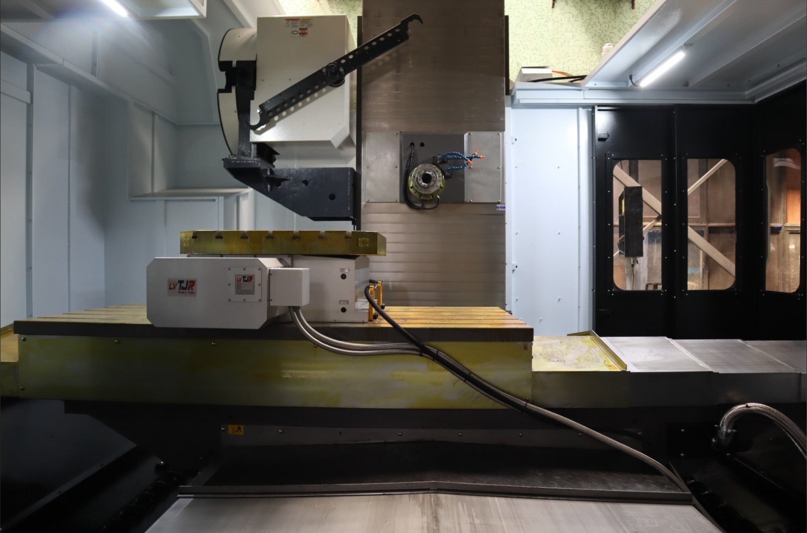
Every V-series machine is checked over full travel with a laser interferometer before it ships, for a positioning accuracy of ±0.005 mm per 300 mm; the LW series is rated at ±0.008 mm per 300 mm.
Send us the housing drawing with the bore tolerances through our inquiry form, and we’ll suggest which setup fits and how to hold the part. See the full range on our machining center page.
Sources
- Harmonic Drive, CSF/CSG Series Component Sets, Recommended Tolerances for Assembly (Table 17)
- Nabtesco, Design notes for the use of RH-N gearboxes
- ZEISS Quality Forum, Concentricity headache, August 2020
- Practical Machinist, Horizontal borer setup for table rotation, August 2019
- TJR, HI-320R Hirth coupling index table and HR-255R worm gear rotary table specifications
- CHANSIN CNC V- and LW-series specifications and option list
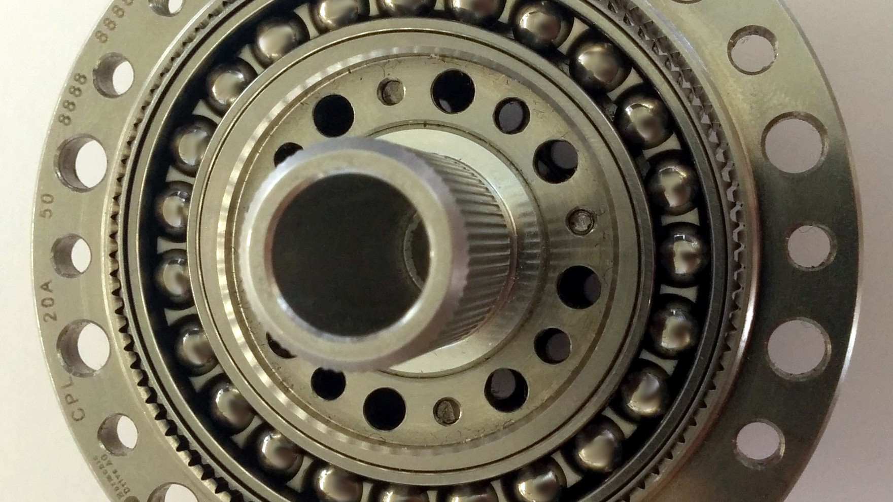
- Featured image: strain wave gear, photo by wdwd, CC BY-SA 4.0, cropped