A machinist asked on a CAM forum which rotary table to buy for his VMC. The first reply was a question back: did he want real fourth-axis motion, or just indexing? For indexing only, almost any table would do, given the right control option and a spare serial port. For real fourth-axis motion on his machine, the builder would only back a table fitted with its own drive and motor.
He wanted the real thing. Another reply put it bluntly: if the machine wasn’t prepared for a fourth axis at the factory, expect a field retrofit and a hefty bill, so order the axis with the machine.
So the first decision isn’t the faceplate size. It’s whether the fourth axis is a real controlled axis that moves together with X, Y and Z, and that’s best settled when you order the machine. After that, three numbers size the rotary: its center height against your part diameter and Z room, the part weight it can carry with or without a tailstock, and the brake torque against your cut.
Rotary table sizes compared
The figures below are TJR’s published specifications for its worm-gear AR series, a typical air-brake rotary for VMCs and drill-tap centers.
| Faceplate | 125 mm | 170 mm | 210 mm | 250 mm |
|---|---|---|---|---|
| Center height | 110 mm | 135 mm | 160 mm | 160 mm |
| Max swing over the table (2 × center height) | Ø220 | Ø270 | Ø320 | Ø320 |
| Part load, faceplate only / with tailstock | 50 / 100 kg | 75 / 150 kg | 75 / 150 kg | 75 / 150 kg |
| Clamping torque, air brake / hydraulic brake | 128 N·m / — | 304 / 540 N·m | 304 / 540 N·m | 304 / 540 N·m |
| Driving torque | 88 N·m | 284 N·m | 284 N·m | 284 N·m |
| Motor housing, distance from rotary axis | 302 mm | 336 mm | 336 mm | 336 mm |
| Rotary weight without motor | 34 kg | 50 kg | 55 kg | 55 kg |
Notice that the 210 and 250 mm tables share the same center height, load rating and brake torque. The 250 mainly gives you a bigger faceplate for a chuck or fixture plate. If your parts don’t need the extra face, the 210 does the same job.
Wide tables on heavy machines take the bigger hydraulic-brake sizes. TJR’s 320 mm table has a 210 mm center height, carries 150 kg on the faceplate or 350 kg with a tailstock, and clamps at 1,128 N·m. The 400 mm table goes to 255 mm, 200/500 kg and 1,962 N·m.
How far can you trust one maker’s figures? We compared the 200 mm class across four makers. Center height and drive torque agree closely: Tsudakoma also uses 160 mm on its RWA-200, Haas 152 mm on the HRT210, and both rate drive torque at about 285 N·m.
Load ratings and brake torque don’t. Haas rates the HRT210 at 38.6 kg unsupported, Tsudakoma the RWA-200 at 125 kg. Nikken lists 303 N·m of brake torque for its CNC202 and Haas 271 N·m, close to TJR’s 304, while Tsudakoma’s dual-taper air clamp holds 800 N·m.
So use the table above to understand the trade-offs, then read the load and brake lines on the data sheet of the table you’re actually buying.
1. The control: a real axis or a separate indexer
Beyond the rotary itself, its motor, cables and servo drive, a fourth axis that’s part of the CNC needs a set of small hardware and PLC software set aside for it when the machine is built. TJR calls this the reserved fourth-axis interface. With it in place, the rotary can move in the same block as X, Y and Z, which is what helical grooves, cam profiles and wrapped toolpaths need.
Without it, the machine builder may still be able to retrofit the axis, at a price.
The cheaper route is a standalone controller. It works on any control that can spare an M-code with a completion signal, but the rotary only indexes: it turns, stops, then the machine cuts. That’s fine for drilling holes around a flange. It rules out anything that needs the rotary moving during the cut.
Mount it the standard way, too. On a VMC, a rotary turning about X is the A axis, and the right-hand rule sets which way is positive. A programmer on the same forum described shops where rotaries were mounted the non-standard way and post processors had to be reworked to suit; in one case the A-axis output came out 180° off.
If you’re not sure whether your work needs simultaneous motion or just indexing, our comparison of 4-axis simultaneous and 3+1 indexing goes through the difference part by part.
2. Center height, part diameter and Z room
The center height decides two things at once. A part can’t be larger than twice the center height or it hits the table as it turns, and at exactly that size it just touches, so leave some clearance. Riser blocks lift the limit. And everything you add above the table eats into the distance between the spindle nose and the table, which is what’s left for the toolholder and the tool.
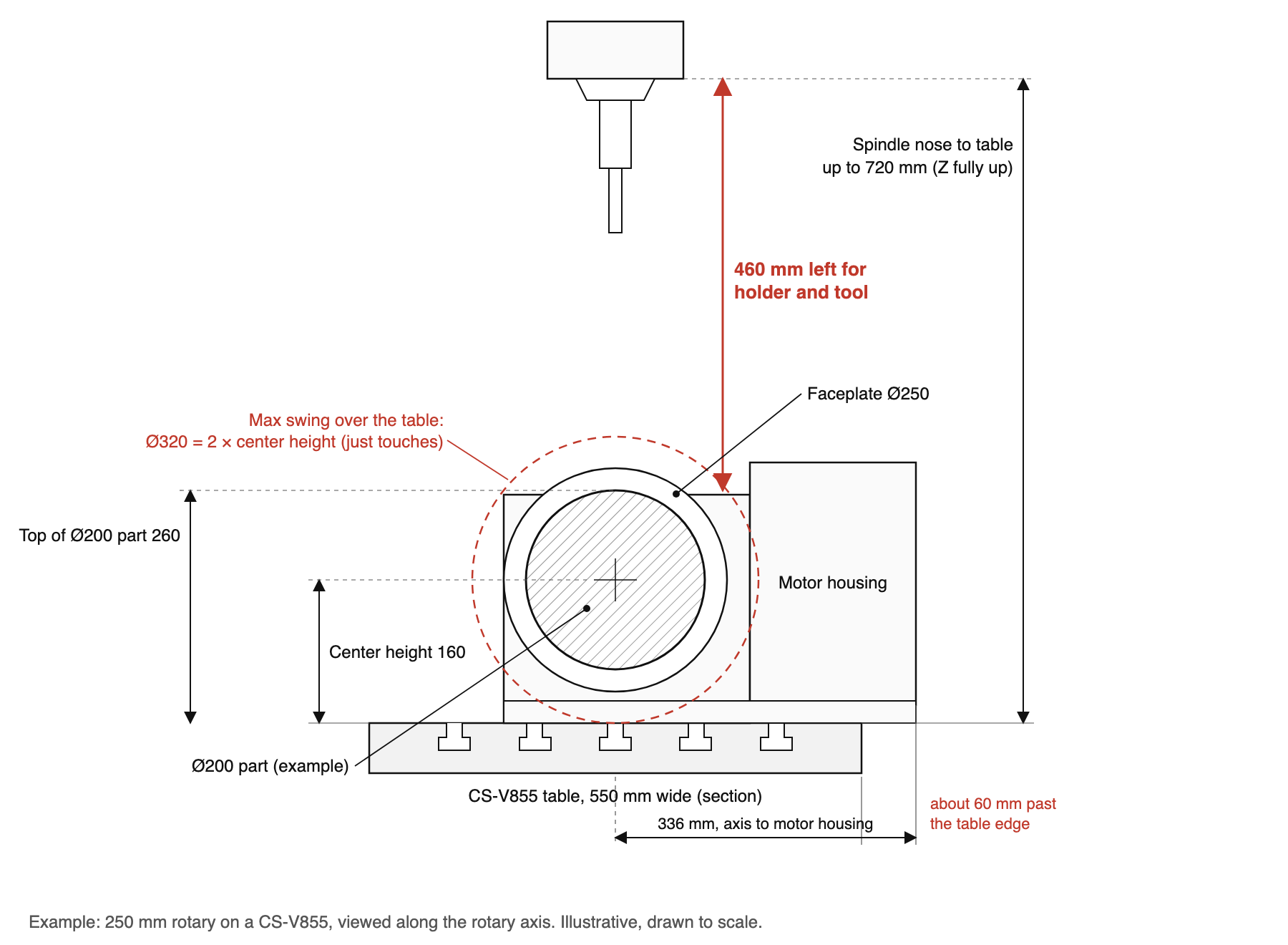
Take a CS-V855: spindle nose to table 120 to 720 mm, table 1000 × 550 mm. With a 250 mm rotary at 160 mm center height, the top of a Ø200 part sits 260 mm above the table. That leaves 460 mm for holder and tool with Z fully up, which is plenty.
On a CS-T6 drill-tap center (150 to 450 mm), a 125 mm rotary at 110 mm puts the top of a Ø150 part at 185 mm, leaving 265 mm. Tighter, but workable for short BT30 tooling.
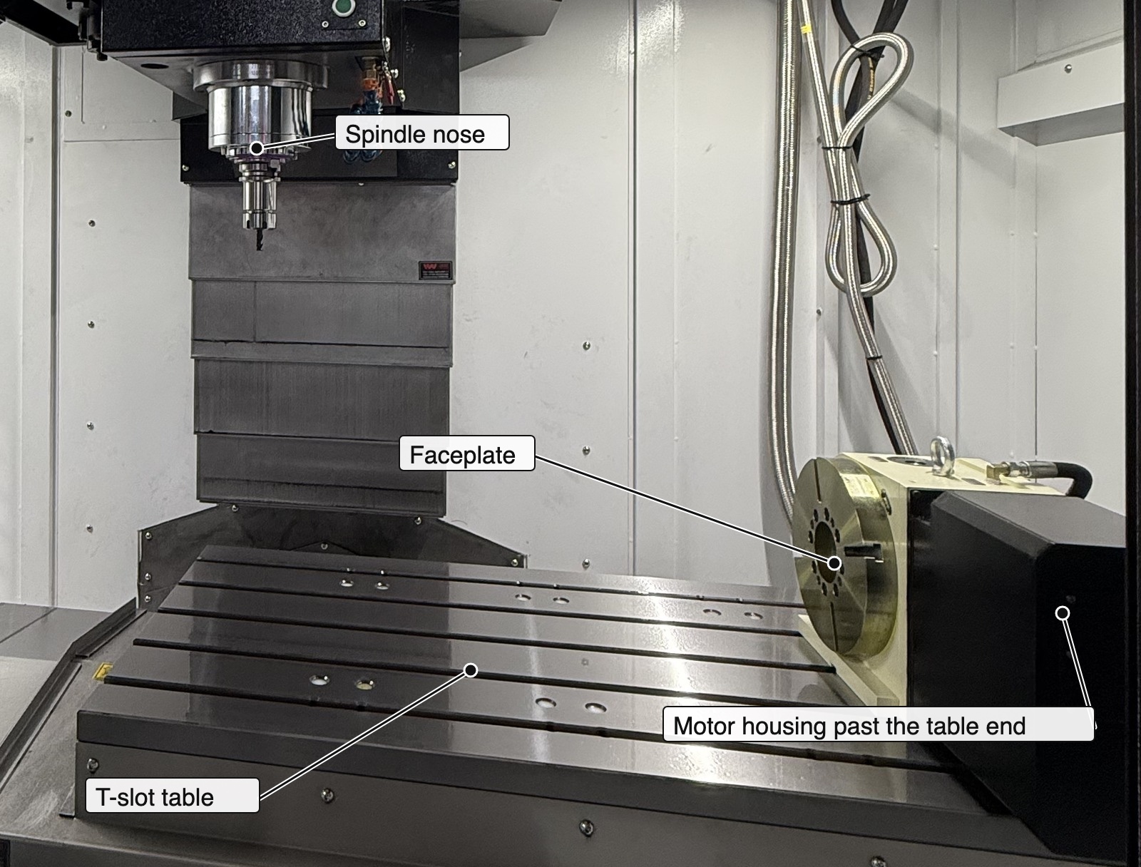
Then look sideways. The motor housing on a 210 or 250 mm table ends 336 mm from the rotary axis. Put that axis on the center T-slot of a 550 mm wide table and the housing sticks out about 60 mm past the edge. TJR’s advice is to measure from the center slot to the door or guard with Y at its home position, and pick a model with a shorter or rear-mounted motor if it won’t clear.
3. Part weight, and when you need a tailstock
With the part hanging off the faceplate, a 210 or 250 mm table is rated for 75 kg. Support the far end with a tailstock and that doubles to 150 kg. A steel shaft Ø100 × 500 mm weighs about 31 kg, so the faceplate alone carries it. Make it Ø150 × 600 mm and it’s about 83 kg: over the limit without a tailstock, comfortable with one. The same part in aluminium is about 29 kg.
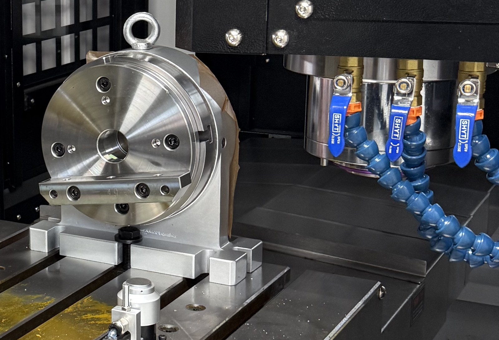
Long or awkward parts usually end up on a bridge plate between the rotary and the tailstock, sometimes on riser blocks. TJR makes a useful point here: if a light part only needs a big swing, a smaller rotary on riser blocks can do it for less weight and money than a bigger one.
The exception is an offset cradle fixture, where the part sits well off the axis. That load wears the worm gear, so tell the supplier before you order.
4. Brake torque, accuracy and air supply
When the rotary indexes and clamps, the brake holds the cut. An air brake on a 170 to 250 mm table holds 304 N·m. At 80 mm from the axis, that’s 3.8 kN of tangential cutting force. At 150 mm it’s only about 2 kN.
The hydraulic brake version holds 540 N·m. TJR’s own rule of thumb matches: air brake for aluminium and copper, hydraulic for cast iron and steel.
The brake only helps when the rotary is clamped, though. During a simultaneous cut it’s released, and the driving torque in the table above is what holds the cut.
These worm-gear tables index to 20 arc-seconds, with 6 arc-seconds repeatability (40 arc-seconds for the 125 mm size). At 100 mm from the axis, 20 arc-seconds is about 0.01 mm. If your drawing asks for tighter angles, TJR points to its hydraulic-brake HR series for about 15 arc-seconds, or an add-on rotary encoder. For positioning-only work there’s also the fixed-step indexer, about ±5 arc-seconds, but it only stops at 1° or 5° steps and can’t cut while turning.
The drive matters too. All the tables above use a worm and worm gear, a widely used and cost-effective design, with backlash you can take up by shifting a dual-lead worm. A roller-cam drive preloads cam followers against the cam instead, so TJR rates it at zero backlash.
That helps when you contour in both directions and want the same finish either way. Direct-drive motors have no gear at all, so no backlash or gear wear, and reach 200 rpm in TJR’s comparison; their precision then depends on the angle encoder fitted.
One maintenance point catches people out. The air brake is switched by a solenoid valve inside the rotary. Wet shop air rusts it until it sticks, so an air brake needs a filter-regulator set or an air dryer on the supply.
Which size fits your machine
Choose a 125 mm table if you run a drill-tap center with a table around 420 to 450 mm wide and your parts are aluminium, up to about Ø200 and 50 kg.
Choose 170 mm if the parts are longer or heavier and you’ll add a tailstock on a drill-tap center.
Choose 210 mm for most work on a VMC with a 500 to 600 mm wide table. Choose 250 mm only when you need the larger faceplate for a chuck or fixture plate.
Choose 320 or 400 mm hydraulic-brake tables for 700 to 900 mm wide tables on heavy machines, with parts up to about Ø400 or Ø500. Choose the hydraulic brake on smaller sizes for steel, cast iron or heavy side cuts far from the axis.
Choose a roller-cam drive when backlash in both directions shows up on your parts. Choose a fixed-step indexer when the job is positioning only and the angle tolerance is tighter than a worm-gear table holds.
How we supply the fourth axis
We fit the fourth axis at the factory, not as a later add-on. The rotary, servo drive, control axis option and cabling are all configured before the machine ships, and the axis runs simultaneously with X, Y and Z. It’s set up on whichever of our control options you order.
- Drill-tap centers: 125 mm rotary, or 170 mm with tailstock and L-block
- CS-V6: 170 mm rotary, matched to its 700 × 420 mm table
- Other V- and L-series machining centers up to 600 mm wide tables: 210 mm rotary, or 250 mm with tailstock and L-block
- L-series machines with 700 to 900 mm tables: 320 or 400 mm hydraulic-brake rotary
- Air or hydraulic brake, roller-cam drives, and fixed-step indexers for positioning work, all available as options
Before you sign the order, check that the configuration sheet says: a controlled fourth axis with simultaneous motion, not a standalone indexer; the rotary size and brake type; a tailstock and L-block if your parts are long or heavy; who supplies the air dryer or filter set; and a layout drawing showing the motor housing clear of the guards with Y at home. You can see the machines on our machining center page.
Send us the part drawing with material and batch size through our inquiry form. We’ll work out which machine and rotary size fit the part, estimate the cycle time and send you a quote for the complete four-axis setup.
FAQ
Is a 4th axis trunnion table the same as a rotary table? Close, but not quite. A rotary with a tailstock and a bridge plate between them works as a single-axis trunnion, holding parts on both ends. A tilting trunnion that also rotates the part is a two-axis, five-axis setup.
Can I add a 4th axis to my VMC later? Often yes, if the machine was built with the reserved axis interface. If not, it’s a costly retrofit, or a standalone controller that only indexes.
Do I need a tailstock? For shafts and long parts, usually yes. On the tables above it doubles the rated part load and cuts deflection at the far end. Short, compact parts usually run fine on the faceplate alone.
Sources
- TJR Precision Technology, General Catalog (PDF): AR series specifications, and the rotary selection notes (material, accuracy, load, Y-axis interference, reserved fourth-axis interface, air supply)
- TJR Precision Technology, AR-250R specification page
- TJR Precision Technology, Can You Add a 4th Axis to an Existing CNC Machine?, July 2026
- TJR Precision Technology, Roller Drive and Comparison of Transmission Mechanisms
- Koma Precision / Tsudakoma, NC Rotary Tables Standard Models (RN-100, RWA-160 to 320)
- Haas Automation, HRT210 specifications
- Nikken Kosakusho, CNC Rotary Tables for FANUC (CNC202LFA)
- CHANSIN CNC catalog 2026: CS-V855, CS-T6 and V/L-series machine data