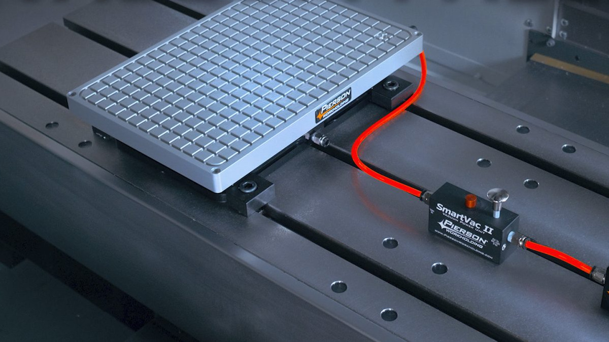
Picture a 6 mm aluminum cover plate. It needs a finished top face, a row of through-holes and the outside profile, all in one setup. Clamps on the edges get in the cutter’s way, so a vacuum table looks like the obvious answer: the whole top is open. Then the drill breaks through the first hole, and air rushes straight into the chamber that’s holding the part down.
So the real question isn’t vacuum or clamps. It’s which method is still holding the part at the end of the last operation, with coolant running. Vacuum wins when the seal survives every opening and the side loads stay moderate. Clamps win when the finished shape leaves little sealed area, or when the job needs heavy side cuts.
What changes on the machine
| Decision | Vacuum table | Mechanical clamps |
|---|---|---|
| Top access | Few top obstructions | Allow for clamp positions |
| Holding after holes | Track sealed regions | Track remaining contact |
| Side load | Friction and stops | Stops and clamp reaction |
| Wet cutting | Protect vacuum circuit | Manage chips and coolant |
| Setup space | Fixture plus connections | Fixture plus clamp reach |
1. The sealed area left after each hole sets the grip
The pump doesn’t pull the part down. It removes the air underneath, and the atmosphere does the pushing. So the grip comes from three things working together: how much area stays sealed, how much pressure difference the pump can hold against leaks, and friction.
Schmalz gives the side holding force as F = A × Δp × μ: sealed area, times pressure difference, times friction. Every 100 mbar of pressure difference gives roughly 1 N/cm² of downforce, and friction between the part and the plate usually sits between 0.2 and 0.5.
Schmalz works through an example: 600 cm² of aluminum at 800 mbar, with μ = 0.25, gives about 1,200 N of side holding force, enough in their example for roughing at around 400 cm³/min. Now let a few through-holes vent into that chamber. If the vacuum level drops to 400 mbar, the same formula leaves about 600 N. That’s half the grip, and the cutter is pushing just as hard as before.
Pierson puts the same limit in shop terms: a 3-inch square part gets about 126 lbf of downforce, a 10-inch square about 1,400 lbf. They call vacuum workholding “often a secondary choice”. It’s what you reach for when a vise can’t hold a thin part, not a way to cut as hard as you would in a vise.
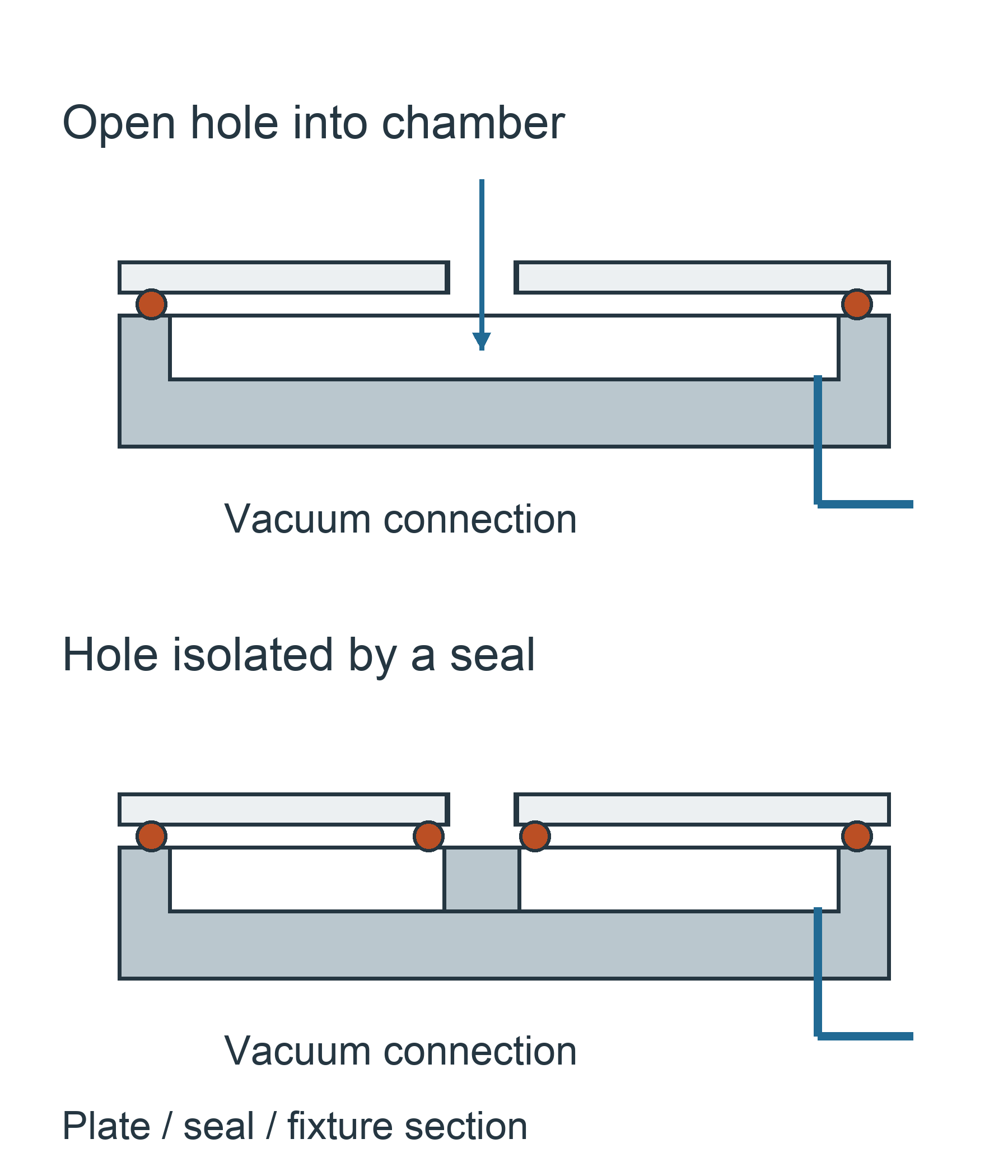
Through-holes don’t rule vacuum out. They just have to sit outside the vacuum. Pierson’s advice is to run a gasket around every through-hole in the top plate, so the cutter can break through without venting the chamber.
For thin features, like the middle of a letter O, they leave 0.005 to 0.010 in (about 0.13 to 0.25 mm) of skin at the bottom to keep the sealed area large, then break the slug out by hand.
DATRON takes a different route on its own tables: a permeable sacrificial layer that the cutter can run into, with the vacuum drawn through it. Both approaches work, but they’re different systems, so when someone offers you a vacuum table, ask which one it is.
Either way, draw the seal layout under your finished part, not under the blank, because the blank is the easy case.
2. Give side loads somewhere to go
Pierson calls side loads the enemy of vacuum work. The downforce can be high and the part will still slide if the cut pushes it sideways. Stops, pins or a shallow pocket in the top plate give that push a hard surface to meet. Smaller, sharper cutters help as well: instead of one 1/2-inch-wide cut around a part, Pierson suggests four passes at 1/8 inch.
Clamps bring much more holding force, and with stops or clamps that push against the cut direction, a solid reaction to side loads. What they cost you is access. Low-profile edge clamps can leave most of the top face open, so clamping doesn’t automatically mean a second setup.
Put the clamping force over supported areas, or you’ll bow a thin plate before the first cut. For the wider fixture questions, such as datums, access and checking, see our CNC workholding guide.
3. Plan for coolant in the vacuum line
With flood coolant, some of it can get drawn into the vacuum circuit, through a worn seal or a hole the drill has just opened. What happens next depends on the vacuum source.
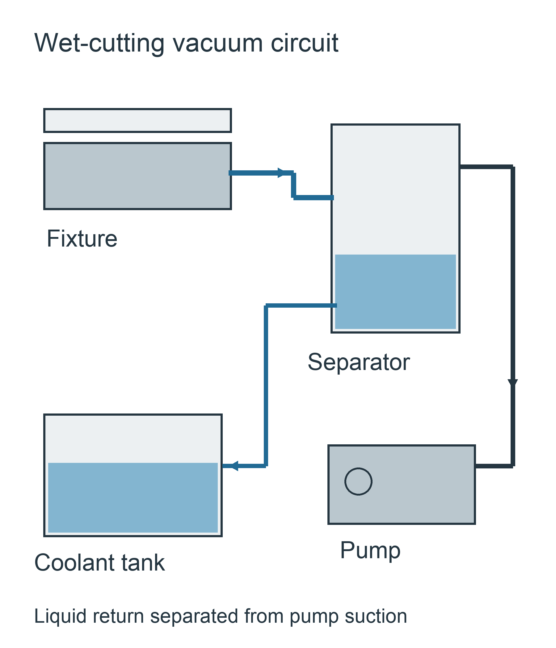
An electric pump that can’t take liquid needs a separator in front of it. Schmalz’s NLS separator, for example, catches the liquid and drains it back while the vacuum holds. Some systems are built differently: Pierson says its own air-driven SmartVac 3 power unit doesn’t need particle filters or coolant traps.
So ask two questions when you spec the system: what kind of vacuum source is it, and where does the coolant it pulls in end up? If coolant can reach a pump that isn’t designed to handle it, the protection isn’t finished.
4. Leave room around the fixture
A vacuum fixture takes up more of the table than its top plate. Count the base, the stops, the fittings and the bend radius of the hose. Then check the stack height against your tool lengths: every millimeter the fixture adds comes out of the Z room you have left for tools.
The pump also needs a spot beside the machine where someone can service it, and the hose needs a route that stays clear of the door, the moving axes and the chip discharge. Treat all of this as part of the machine layout, not as an accessory you find a place for on delivery day.
Choose by the finished part
Choose vacuum if the plate benefits from support across its whole underside, the seal layout survives every through-cut, and the coolant path is designed in. Budget time for making top plates and gasket grooves, because that’s part of the setup cost.
Choose clamps if the finished shape leaves too little sealed area, or the job calls for heavy side cuts. Edge clamps or a different operation order can often keep most of the access you wanted vacuum for.
Setting up a V855 for thin plate work
Our V855 has 800 × 550 × 550 mm of travel and a 1000 × 550 mm table. For thin plate work we can fit a vacuum table with its pump, sized to your part, and lay out the stops, fittings and hose route with the fixture rather than after it.
Before you sign off the order, have the configuration list name five things: the fixture size, how it mounts, where the pump sits, how the hose runs and what handles the coolant. Send us your drawing with the flatness requirement, batch size and operation order, including every through-cut, and we’ll come back with a configuration and a quote.
FAQ
Can a vacuum table hold a part with through-holes?
Yes, if each hole is sealed off from the vacuum, or if the table is built to draw vacuum through a permeable layer. A plain chamber with open holes over it loses vacuum as soon as the drill breaks through.
Can vacuum workholding run with flood coolant?
Yes, when the circuit is designed for it. Coolant can get drawn in, so you need either a vacuum source that tolerates liquid or a separator in front of the pump, plus somewhere for the collected liquid to drain.
Will a 1000 × 550 mm table take a fixture that size?
Usually not. Fittings, stops and the hose need room beyond the plate itself, so plan the fixture smaller than the table unless its maker has designed an overhanging top plate. Either way, check its clearance across the full X and Y travel.
Sources and Method
- Schmalz: Vacuum clamping technology, holding-force formula and worked example
- Pierson Workholding: SmartVac FAQs and vacuum workholding tips, through-hole gaskets, skin thickness, side loads and downforce examples
- DATRON: Work Holding, permeable sacrificial-layer tables
- Schmalz: NLS assembly instructions, 30.30.01.03301, liquid separation in a wet-cutting vacuum system
- Featured image: Pierson Workholding
The 400 mbar case is our own illustration using the Schmalz formula. V855 figures are from our current product parameter sheet.