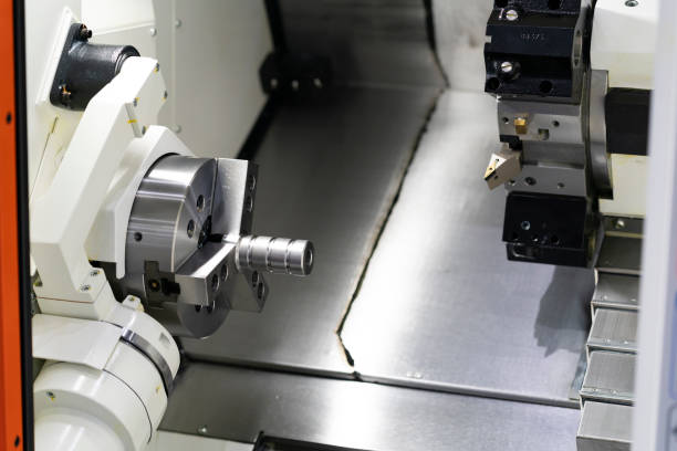
When selecting a CNC turning center, engineers often compare the cnc lathe Y-axis and C-axis. Both expand machining capabilities, but they perform different functions. A C-axis controls spindle rotation and angular positioning. A Y axis provides linear movement perpendicular to the X and Z axes.
This distinction matters when machining complex parts. A CNC lathe with C-axis control can perform angular positioning and certain milling operations. However, C-axis capability alone does not provide the physical offset movement needed for many off-center features. Without a suitable Y-axis arrangement, machining eccentric flats, offset holes, and certain keyways may require additional setups or equipment.
Understanding these differences helps manufacturers select the right CNC lathe configuration. It also prevents buyers from paying for features that their parts do not require—or overlooking an axis that is essential for production.
1. Fundamental Kinematics: Rotary Indexing (C Axis) vs. Linear Motion (Y Axis)
The most important difference between the Y axis and C axis is their motion type. One controls angular position, while the other controls linear position.
Understanding this distinction provides the foundation for evaluating CNC turning and milling capabilities.
1.1 What Is the C Axis on a CNC Lathe?
The C axis controls the angular position of the spindle and workpiece around the spindle centerline.
Unlike conventional turning, where the spindle rotates continuously, C-axis operation allows the control system to position the workpiece at a specified angle.
For example, the spindle can position a workpiece at 0°, 90°, 180°, or 270°. The machine can then perform milling or drilling at the selected angular position, depending on its live-tooling configuration.
Common C-axis applications include:
- Drilling holes at specified angular positions.
- Milling features around a cylindrical surface.
- Machining radial slots and grooves.
- Creating equally spaced holes.
- Performing indexed milling operations.
A C axis is especially useful when parts require features at different angular positions around their circumference.
However, C-axis indexing changes the workpiece angle. It does not independently move the cutting tool sideways relative to the spindle centerline.
1.2 What Is the Y Axis on a CNC Lathe?
The Y axis provides linear movement perpendicular to the X and Z axes.
On a typical CNC turning center, the Z axis follows the spindle centerline, while the X axis controls radial tool movement. The Y axis adds another direction of linear movement.
This additional movement allows the cutting tool to reach positions above or below the X-Z machining plane.
Common Y-axis applications include:
- Off-center drilling.
- Eccentric hole machining.
- Milling offset flats.
- Machining parallel surfaces away from the centerline.
- Producing certain slots and keyways.
- Performing more complex milling operations in one setup.
The Y axis is particularly useful when a part contains features that do not lie on the spindle centerline or standard X-Z machining plane.
1.3 CNC Lathe Y Axis vs. C Axis: Key Differences
| Comparison Factor | C Axis | Y Axis |
|---|---|---|
| Motion type | Rotary motion | Linear motion |
| Main function | Controls spindle angular position | Controls tool position perpendicular to the X-Z plane |
| Movement direction | Around the spindle centerline | Along the machine’s Y direction |
| Main application | Angular indexing and circumferential machining | Off-center milling and drilling |
| Typical features | Radial holes, indexed slots, circumferential patterns | Offset flats, eccentric holes, off-center features |
| Required equipment | C-axis spindle control and suitable tooling | Y-axis slide or an equivalent machine arrangement |
| Main limitation | Does not create independent Y-direction travel | Requires suitable travel, rigidity, and tool access |
These axes are complementary rather than interchangeable.
A machine with both C-axis and Y-axis capabilities can handle a wider range of turning and milling operations. However, the actual machining range still depends on spindle control, live tooling, tool orientation, travel limits, and machine structure.
2. Machining Limits of C Axis Alone: Polar Coordinate Interpolation
A CNC lathe with C-axis control can perform many milling operations without a Y axis. However, its machining range depends on the geometry of the part and the available interpolation functions.
Polar coordinate interpolation is one important method for machining certain features using X- and C-axis movements.
2.1 How Polar Coordinate Interpolation Works
Polar coordinate interpolation converts movements between Cartesian coordinates and polar coordinates.
Instead of controlling a tool through two conventional linear axes, the CNC control coordinates linear movement with spindle rotation.
On a turning center, this function can allow the X axis and C axis to work together for selected milling operations.
For example, a machine may use polar interpolation to produce a slot or flat feature on the end face of a cylindrical component.
The basic concept is:
- The X axis controls radial position.
- The C axis controls angular position.
- The CNC control coordinates both movements.
- A suitable live tool performs the cutting operation.
This method is useful when the required feature can be generated within the machine’s available motion and tool orientation.
2.2 What Can a C-Axis-Only CNC Lathe Machine?
A CNC lathe with C-axis control and live tooling can perform several useful operations.
Examples include:
End-face milling
The machine can mill selected features on the workpiece end face, subject to its tooling and interpolation capabilities.
Angular hole drilling
The spindle can index the workpiece to specific angles. A live tool can then drill holes at those positions.
Circumferential slots
The C axis can position or coordinate the workpiece for slots around its circumference.
Indexed flats
Certain flats can be machined by positioning the workpiece at a specified angle and using an appropriate cutting tool.
These operations can reduce the need to transfer parts to a separate milling machine.
However, the presence of a C axis does not mean every milling feature can be completed in one setup.
2.3 Why C Axis Alone Cannot Replace Y-Axis Movement
Consider a cylindrical component with an eccentric hole located away from the spindle centerline.
The C axis can rotate the workpiece to a required angular position. However, rotation alone cannot provide the independent linear offset needed to place the cutting tool at every required position.
Similarly, a flat surface parallel to the spindle axis but offset from the centerline may require Y-direction movement.
Without a true Y axis or another suitable machine arrangement, the operation may require:
- A special offset tool.
- An alternative machining setup.
- A secondary milling operation.
- A different machine configuration.
The exact limitation depends on the feature geometry and available tool orientation.
2.4 When Polar Interpolation Is Not Enough
Polar interpolation is not a universal substitute for Y-axis movement.
It is useful when the required geometry can be represented through coordinated radial and angular movement. However, it does not automatically provide arbitrary linear tool positioning in the Y direction.
Before purchasing a C-axis-only turning center, engineers should review the actual part drawings.
Pay particular attention to:
- Hole center positions.
- Offset dimensions.
- Flat locations.
- Slot orientation.
- Required machining approach.
- Tool clearance.
- Tolerance requirements.
This drawing-based assessment is more reliable than judging machine capability from the number of axes alone.
3. The Power of Y Axis: Off-Center Milling, Keyways, and Flat Surfaces
A Y-axis CNC lathe adds an important degree of machining freedom. It allows the cutting tool to move beyond the standard X-Z machining plane.
When combined with C-axis control and live tooling, it can support more complex milling operations in a single setup.
3.1 Off-Center Milling
Off-center milling is one of the most important applications of a Y-axis turning center.
Some components contain flats, pockets, or grooves that are not located on the spindle centerline.
A Y axis allows the cutting tool to reach these offset positions through controlled linear movement.
Potential applications include:
- Eccentric flats on cylindrical parts.
- Offset rectangular pockets.
- Parallel surfaces away from the centerline.
- Selected side-milled features.
- Complex machined profiles.
For example, a cylindrical component may require a flat surface at a specified offset from its centerline.
With suitable Y-axis travel and live tooling, the machine can position the tool at the required location and mill the feature.
This can reduce additional clamping and repositioning operations.
3.2 Off-Center Drilling
Off-center drilling is another important reason to consider a CNC lathe with Y axis.
A part may require holes at positions that do not align with the spindle centerline or standard radial tool path.
The Y axis provides additional positioning freedom. The C axis can also orient the workpiece when the hole pattern requires a specific angular position.
Together, these axes can support more flexible hole machining.
Typical examples include:
- Eccentric cross holes.
- Offset threaded holes.
- Multiple holes at different angular positions.
- Complex drilling patterns on cylindrical components.
However, the actual capability depends on tool direction, drilling depth, spindle orientation, and available clearance.
3.3 Keyways and Slot Milling
Keyways and slots often require accurate positioning relative to a part’s centerline.
A C axis can position the workpiece at a selected angular location. A Y axis can provide additional linear positioning for features that are offset from the standard machining plane.
This combination can be useful for machining:
- Offset keyways.
- Axial slots.
- Milled grooves.
- Selected side features.
- Multi-position slot patterns.
Not every keyway requires a Y axis. A centered or appropriately oriented feature may be machined using other machine configurations.
The deciding factor is the actual position and geometry of the feature.
3.4 Angled Holes and Complex Milling Features
A Y-axis turning center may also support certain angled or compound machining operations.
However, a Y axis alone does not provide unlimited tool orientation.
The machine may also need suitable live tooling, toolholder angles, interpolation functions, and sufficient clearance.
For more complex features, engineers should check:
- Tool approach direction.
- Required angular orientation.
- Y-axis travel range.
- X-axis and Z-axis travel.
- Toolholder geometry.
- Workpiece interference.
- CNC control functions.
This is especially important when evaluating parts with multiple intersecting holes or complex milled profiles.
3.5 How Y Axis Can Reduce Secondary Operations
Without suitable Y-axis capability, some off-center features may require transferring the workpiece to a separate milling machine.
This can introduce additional handling and setup requirements.
A suitable Y-axis turning center may help manufacturers:
- Complete more features in one setup.
- Reduce workpiece repositioning.
- Improve positional consistency between turned and milled features.
- Reduce work-in-process.
- Simplify production routing.
These benefits depend on part complexity, batch size, cycle time, tooling, and machine utilization.
A Y axis is most valuable when its additional machining freedom solves a recurring production requirement.
4. Structural Engineering: Virtual Y Axis (Wedge Type) vs. True Orthogonal Y Axis
Not every machine described as having Y-axis capability uses the same mechanical structure.
Some turning centers use a conventional orthogonal Y-axis slide. Others use angled slides or compound-axis arrangements to generate equivalent tool movement.
Buyers should understand the mechanical design rather than judge a machine only by its marketing description.
4.1 What Is a True Orthogonal Y Axis?
A true orthogonal Y axis uses a linear slide arranged perpendicular to the X and Z axes.
This provides a direct linear movement in the Y direction.
Its main characteristics include:
- A dedicated Y-axis travel direction.
- Direct positioning control.
- A defined linear guide and drive arrangement.
- Additional flexibility for off-center machining.
The performance of a true Y-axis structure depends on the entire mechanical system.
Important factors include guideway design, slide dimensions, drive stiffness, bearing arrangement, toolholder support, and structural rigidity.
A true orthogonal layout does not automatically guarantee higher rigidity than every alternative design.
4.2 What Is a Wedge-Type or Virtual Y-Axis Arrangement?
Some CNC turning centers use an angled slide or compound motion to create an effective Y-direction tool movement.
The CNC control coordinates movements along the available mechanical axes to position the tool at the required location.
This type of arrangement is sometimes described as a virtual Y axis.
Its actual capability depends on the mechanical design and CNC control implementation.
Potential design considerations include:
- Slide angle and travel.
- Motion conversion accuracy.
- Tool positioning range.
- Guideway support.
- Structural stiffness.
- Compensation and calibration.
- Tool access and interference.
The term “virtual Y axis” does not describe one universal machine architecture. Buyers should request the manufacturer’s axis diagram and machining specifications.
4.3 Comparing Orthogonal and Wedge-Type Structures
| Comparison Factor | True Orthogonal Y Axis | Wedge-Type or Virtual Y Arrangement |
|---|---|---|
| Motion generation | Direct linear Y-axis movement | Coordinated movement through an angled or compound structure |
| Mechanical layout | Dedicated orthogonal slide | Angled slide or equivalent mechanism |
| Tool positioning | Direct Y-direction control | Depends on motion conversion and control |
| Travel characteristics | Defined by dedicated slide travel | Depends on geometry and available axis travel |
| Rigidity | Depends on slide and structural design | Depends on wedge geometry, support, and structural design |
| Programming | Uses configured Y-axis functions | May require specific control functions or compensation |
| Evaluation priority | Slide stiffness, travel, and accuracy | Motion geometry, positioning accuracy, and stiffness |
Neither design should be judged by its name alone.
A well-engineered wedge-type structure may provide suitable performance for its intended applications. Likewise, a true orthogonal Y axis may have limitations if its slide is poorly supported or undersized.
4.4 What Determines Y-Axis Rigidity?
Rigidity affects dimensional accuracy, surface finish, tool life, and vibration behavior during milling.
When evaluating a CNC lathe, buyers should examine several structural factors.
Guideway support
The guideway arrangement influences how the slide supports cutting forces. Its dimensions and contact characteristics matter.
Slide geometry
A larger or better-supported slide may improve resistance to deflection, but size alone does not prove performance.
Drive system
Ball screws, bearings, and drive arrangements influence positioning accuracy and stiffness.
Toolholder overhang
Long tool extensions can increase bending and vibration. A rigid machine still needs suitable tooling.
Cutting force direction
Different milling operations generate different force directions. The machine structure should support the expected load paths.
Thermal stability
Temperature changes can affect machine geometry and positioning. Thermal control and compensation are important for demanding applications.
4.5 How to Verify Machine Structure Before Purchase
Do not rely only on the phrase “Y-axis capable.”
Ask the manufacturer for:
- Machine axis configuration drawings.
- Y-axis travel specifications.
- Slide and guideway structure.
- Positioning accuracy and repeatability data.
- Tooling and live-tooling specifications.
- Sample machining results.
- Relevant rigidity or cutting tests, where available.
For demanding components, request a machining demonstration using a representative workpiece and cutting conditions.
This provides a more practical basis for comparing machine structures.
5. Decision Guide: Evaluating Your Part Prints to Justify Y-Axis Investment
A Y axis can expand machining capability, but it also adds mechanical complexity and investment cost.
The best decision depends on the features in your part drawings and the production requirements.
5.1 Identify Features That May Require Y-Axis Capability
Start by reviewing the part drawing and identifying features that are not located in the standard X-Z machining plane.
| Part Feature | C Axis May Be Sufficient? | Y Axis May Be Needed? |
|---|---|---|
| Angularly positioned radial holes | Often, with suitable live tooling | Depends on hole offset |
| Equally spaced holes around a cylinder | Often | Not always |
| Centered end-face milling | Often, with suitable interpolation | Not always |
| Off-center end-face pockets | Depends on geometry | Often beneficial |
| Eccentric holes | Depends on tool arrangement | Often required |
| Offset parallel flats | Depends on machine configuration | Often required |
| Circumferential grooves | Often | Not usually |
| Complex side-milled profiles | Depends on geometry and tooling | Often beneficial |
| Angled holes | Depends on tool orientation | May be required |
This table provides a preliminary guide, not a universal machining rule.
Some machines can perform selected off-center operations through alternative axis arrangements or special tooling. Always verify the actual machine’s kinematics.
5.2 Evaluate Your Production Process
The decision should also consider how frequently the part requires off-center features.
Ask the following questions:
- How many parts in the production range contain eccentric features?
- Are off-center holes or flats required on most production batches?
- Does the current process require a separate milling setup?
- How much time does workpiece repositioning add?
- Are positional relationships between turned and milled features critical?
- Can the required geometry be produced with existing tooling?
- Will future products require more complex milling operations?
If most parts only need turning and indexed radial drilling, a C-axis turning center may be sufficient.
If off-center milling and drilling are frequent, a Y-axis configuration may provide greater production flexibility.
5.3 Compare the Total Cost of Ownership
The purchase price is only one part of the machine investment.
A useful comparison should include:
- Initial machine cost.
- Tooling and toolholder requirements.
- Programming and operator training.
- Setup and changeover time.
- Secondary machining costs.
- Work-in-process.
- Scrap and rework.
- Maintenance requirements.
- Expected production volume.
A Y-axis machine may have a higher initial price. However, it may reduce secondary operations for parts with complex milling requirements.
The financial benefit should be calculated using actual cycle times, setup costs, labor rates, and production volumes.
5.4 A Practical Selection Framework
Use the following decision logic when comparing machine configurations.
Choose a C-axis turning center when:
- Most operations involve conventional turning.
- Parts require angular indexing.
- Radial holes and circumferential features dominate.
- End-face milling fits the available X-C machining range.
- Off-center milling requirements are limited.
Consider a Y-axis turning center when:
- Parts contain eccentric holes.
- Offset flats or pockets appear frequently.
- Milling features extend beyond the standard X-Z plane.
- Multiple machining setups create significant production costs.
- Future products require more complex turning and milling operations.
Consider a machine with both C and Y axes when:
- Parts require angular indexing and off-center machining.
- Multiple milling features must be completed in one setup.
- Production flexibility is important.
- Part complexity justifies the additional investment.
The final choice should be verified through a machining review using representative part drawings.
6. Frequently Asked Questions About CNC Lathe Y Axis and C Axis
Q1. What is the main difference between the Y axis and C axis on a CNC lathe?
The C axis controls spindle angular position around the workpiece centerline. The Y axis provides linear movement perpendicular to the X-Z plane.
C-axis control supports indexed machining. Y-axis movement supports off-center positioning and milling operations.
Q2. Can a CNC lathe with C axis perform milling?
Yes. A CNC lathe with C-axis control and suitable live tooling can perform various milling and drilling operations.
Examples include radial holes, circumferential slots, and selected end-face features. The available operations depend on machine configuration and CNC functions.
Q3. Can a C-axis CNC lathe machine eccentric holes?
Some eccentric holes may be machined through alternative tool arrangements or machine configurations.
However, C-axis rotation alone does not provide independent Y-direction movement. A true Y axis or another suitable positioning arrangement may be necessary for certain eccentric hole locations.
Q4. Is a Y axis necessary for every CNC turning center?
No. Many production parts only require turning, axial drilling, radial drilling, or indexed milling.
A Y axis becomes more valuable when parts contain off-center features that cannot be efficiently produced with the available X, Z, and C movements.
Q5. What is polar coordinate interpolation on a CNC lathe?
Polar coordinate interpolation coordinates linear and rotary movements to machine selected features.
On suitable machines, X- and C-axis movements can support milling operations on the workpiece end face. It does not automatically replace independent Y-axis travel.
Q6. Is a true Y axis more rigid than a virtual Y axis?
Not in every case.
Rigidity depends on slide geometry, guideway support, drive arrangement, structural design, and cutting force direction.
Buyers should compare machine drawings, technical specifications, and representative cutting results rather than rely only on the axis name.
Q7. Does a CNC lathe with both Y axis and C axis replace a milling machine?
It can consolidate many turning and milling operations for suitable components.
However, it does not replace every milling machine. Part size, tool orientation, spindle power, travel, workholding, and machining requirements determine whether a turning center can complete the entire process.
Conclusion: Choose CNC Lathe Axes Based on Part Geometry
The key difference between a cnc lathe y axis and a C axis lies in their motion and machining functions.
The C axis controls spindle rotation and angular positioning. It supports indexed drilling, circumferential features, and selected milling operations through suitable live tooling and interpolation.
The Y axis provides additional linear movement perpendicular to the X-Z machining plane. It expands access to off-center holes, offset flats, pockets, and other complex milling features.
Machine structure also matters. True orthogonal and wedge-type arrangements generate Y-direction movement through different mechanical designs. Their rigidity and accuracy should be evaluated through actual specifications and machining performance.
For buyers, the most reliable selection method is to review part drawings, identify off-center features, evaluate existing production setups, and compare the total cost of ownership.
A suitable CNC lathe configuration should match the geometry of current parts while supporting realistic future production needs.
CHANSIN provides CNC machining equipment solutions for different turning and milling requirements. Share your part drawings, machining operations, and production targets to discuss a suitable machine configuration.