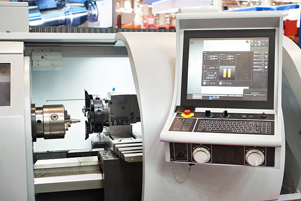
Choosing a CNC lathe and milling combo can help manufacturers reduce setup time and complete more operations in one machine. However, not every machine marketed as a turn-mill solution offers the same machining capabilities. Some CNC lathes only add basic live tooling, while advanced turn-mill centers combine multiple axes, advanced interpolation, and additional workholding options.
This difference matters when machining complex parts. A machine with basic live tooling may handle drilling or simple milling on turned components. However, eccentric holes, off-center slots, angled features, and multi-face machining may require a more advanced axis configuration.
For manufacturers, the right machine depends on part geometry, production volume, machining accuracy, and process requirements. This guide explains how to compare entry-level live-tooling lathes with true turn-mill centers and how to evaluate machine structure, spindle capacity, turret configuration, and CNC control systems before purchasing.
1. Demystifying the “Combo” Machine: Entry-Level Lathes vs. True Turn-Mill Centers
The term “CNC lathe and milling combo” covers different machine configurations. Understanding the differences helps buyers avoid paying for unnecessary functions or purchasing a machine that cannot complete their intended machining operations.
1.1 What Is a CNC Lathe with Live Tooling?
A CNC lathe with live tooling uses driven tools installed in the turret. Unlike conventional static turning tools, live tools rotate to perform operations such as drilling, tapping, and milling.
Common applications include:
- Drilling radial holes on cylindrical parts.
- Milling flats and simple slots.
- Drilling holes on the end face.
- Tapping selected features.
- Machining small keyways or grooves.
The workpiece is usually held by the main spindle. The C-axis function can control spindle orientation and positioning, allowing the machine to perform indexed milling operations.
A basic live-tooling lathe may use X and Z axes for turning, with C-axis positioning and driven turret tools for milling.
This configuration can reduce secondary operations for parts with relatively simple milled features.
However, live tooling alone does not automatically provide full multi-axis turn-mill capability.
1.2 What Makes a True Turn-Mill Center Different?
A more advanced turn-mill center combines turning and milling operations through additional machine axes and coordinated control.
Depending on the model, its configuration may include:
- X-axis and Z-axis for turning.
- Y-axis for off-center and multi-position milling.
- C-axis for spindle orientation and interpolation.
- Driven tools for drilling and milling.
- A sub-spindle for transferring and machining the opposite end.
- Additional turret or milling-head configurations.
- Advanced CNC functions for coordinated multi-axis machining.
The Y-axis is particularly important when a part requires features that are offset from the spindle centerline.
For example, a component may require an eccentric hole or a slot positioned away from the central axis. A machine with suitable Y-axis travel can position the tool relative to the workpiece centerline more directly.
However, Y-axis capability is not the only way to produce every off-center feature. Certain geometries may be machined through suitable C-axis indexing, tool offsets, or alternative machine configurations.
The correct choice depends on the actual part drawing and machining strategy.
1.3 Entry-Level Live-Tooling Lathe vs. Advanced Turn-Mill Center
| Comparison Factor | Live-Tooling CNC Lathe | Advanced Turn-Mill Center |
|---|---|---|
| Main operations | Turning and selected milling | Integrated turning and complex milling |
| Typical axes | X, Z, C, depending on model | X, Z, C, Y, and additional axes depending on model |
| Driven tools | Commonly available | Available with more advanced configurations |
| Off-center machining | Limited by machine configuration | Greater flexibility with suitable Y-axis capability |
| Opposite-end machining | May require manual repositioning | Can use a sub-spindle when configured |
| Complex interpolation | Depends on CNC system and axis configuration | Designed for more coordinated multi-axis operations |
| Typical application | Turned parts with simple secondary features | Complex parts requiring multiple integrated operations |
Buyers should evaluate the actual axis list and machine specifications rather than rely on marketing terms such as “5-axis,” “multi-function,” or “turn-mill.”
1.4 When Do You Need a Y-Axis or Sub-Spindle?
Not every production line needs a fully equipped turn-mill center.
A live-tooling lathe may be sufficient for parts that mainly require turning, radial drilling, and simple indexed milling.
A Y-axis becomes more valuable when parts include:
- Eccentric holes.
- Off-center milling.
- Parallel flats at different positions.
- Complex side slots.
- Features requiring controlled movement away from the spindle centerline.
A sub-spindle is useful when the part requires machining on both ends.
After the main spindle completes its operations, the sub-spindle can receive the workpiece and support additional machining. This can reduce manual repositioning and help maintain alignment between operations.
However, sub-spindle transfer accuracy depends on spindle synchronization, workholding, machine condition, and the transfer process.
Practical selection rule: Start with the most complex feature on your part drawing. Then identify the axes, tools, and workholding functions required to machine it.
2. Assessing Machining Capabilities: Maximum Turning Diameter and Milling Capacity
Machine selection should begin with the dimensions and geometry of the parts to be produced.
A machine may have an impressive spindle rating but still be unsuitable if its turning diameter, tool clearance, or milling travel does not match the workpiece.
2.1 Maximum Turning Diameter and Swing Over Bed
Maximum turning diameter describes the largest workpiece diameter that a machine can process under specified conditions.
Buyers should distinguish between:
- Swing over bed.
- Maximum turning diameter.
- Maximum turning diameter over the carriage or slide.
- Chuck diameter and workholding clearance.
These values are not interchangeable.
A machine may have a large swing over bed, but the actual turning capacity can be smaller because of the turret, toolholder, chuck, or other structural limitations.
Before purchasing, confirm the maximum turning diameter with the intended chuck and tooling configuration.
2.2 Maximum Turning Length and Workpiece Capacity
Maximum turning length determines how much axial distance the machine can process.
This parameter matters for shafts, sleeves, long cylindrical components, and other extended parts.
However, the stated turning length does not always equal the usable machining length.
Buyers should also check:
- Distance between spindle nose and tailstock or sub-spindle.
- Chuck and jaw dimensions.
- Toolholder clearance.
- Maximum bar capacity.
- Tailstock travel, if applicable.
- Sub-spindle travel and transfer range.
- Interference between tools and workholding components.
For bar-fed production, spindle bore and bar feeder compatibility are also important.
A machine with sufficient turning length but inadequate bar capacity may not suit the intended production process.
2.3 Evaluating Live-Tooling Power and Torque
Driven-tool power and torque influence milling performance.
Power describes the rate at which the motor performs work. Torque describes the rotational force available at the tool.
Both matter when selecting a machine for different materials and cutting conditions.
For example:
- Small drills may require relatively modest torque.
- Larger end mills may require higher torque.
- Stainless steel and other difficult-to-cut materials may demand suitable torque and rigidity.
- High-speed finishing may prioritize spindle speed and dynamic performance.
Buyers should request the driven-tool spindle’s rated power, torque curve, maximum speed, and operating duty conditions.
Do not compare machines using motor power alone. A high power rating does not guarantee sufficient torque at the speed required for a particular cutting operation.
2.4 Matching Milling Capacity to Part Geometry
Milling capacity depends on more than the driven-tool motor.
It also depends on:
- Toolholder rigidity.
- Turret stiffness.
- Axis travel.
- Machine structure.
- Spindle indexing accuracy.
- Cutting tool dimensions.
- Workpiece clamping.
- CNC interpolation capability.
For eccentric holes and side slots, buyers should check whether the machine has the required Y-axis travel or an alternative machining arrangement.
For angled surfaces or complex contours, the required tool orientation and interpolation functions may influence whether a standard live-tooling turret is sufficient.
A useful approach is to provide the supplier with representative part drawings. Ask for a machining review that identifies the required operations and machine configuration.
2.5 A Practical Machining Capacity Checklist
| Parameter | What Buyers Should Confirm |
|---|---|
| Maximum turning diameter | Actual usable diameter with selected tooling |
| Maximum turning length | Usable axial machining range |
| Chuck size | Compatibility with the workpiece |
| Spindle bore | Bar material and workholding requirements |
| Main spindle power | Cutting requirements and duty conditions |
| Main spindle torque | Material and roughing requirements |
| Driven-tool power | Milling and drilling requirements |
| Driven-tool torque | Cutting load at required speed |
| Driven-tool speed | Suitable range for planned tools |
| Y-axis travel | Required off-center machining range |
| C-axis capability | Indexing and interpolation requirements |
| Sub-spindle | Opposite-end machining and transfer requirements |
3. Structural Configurations: Slant Bed vs. Flat Bed and Turret Specifications
Machine structure affects rigidity, chip evacuation, thermal behavior, tool access, and long-term machining consistency.
For a CNC turn-mill machine, buyers should compare the bed structure and turret arrangement alongside the axis configuration.
3.1 Slant Bed CNC Lathes: Chip Evacuation and Accessibility
Slant bed machines use an inclined bed structure to support the machine’s slide system.
Common designs include 30-degree and 45-degree configurations, although actual angles vary by manufacturer and model.
The inclined layout can provide several practical advantages:
- Gravity-assisted chip evacuation.
- Improved access to the machining area.
- Convenient integration of chip conveyors.
- Potentially more efficient coolant and chip management.
- Compact machine layouts in selected designs.
Chip evacuation is especially important in continuous production.
Long chips can wrap around tools or workpieces, interfere with machining, and require additional operator intervention.
A suitable slant bed structure can help guide chips toward the collection area.
However, chip flow also depends on material, tool geometry, cutting conditions, coolant delivery, and enclosure design.
3.2 Flat Bed CNC Lathes: Structural and Application Considerations
Flat bed lathes use a horizontal bed arrangement.
They are common in conventional turning applications and may offer advantages in certain large-workpiece or specialized machine designs.
Potential considerations include:
- Machine size and workpiece support.
- Structural layout for large components.
- Tool access and operator requirements.
- Chip collection and coolant management.
- Integration with specific production processes.
A flat bed machine is not automatically less rigid than a slant bed machine.
Actual rigidity depends on the bed structure, casting design, guideways, material, component dimensions, and machine assembly.
Buyers should compare machine specifications and test results instead of judging rigidity from bed angle alone.
3.3 Slant Bed vs. Flat Bed: Key Differences
| Comparison Factor | Slant Bed | Flat Bed |
|---|---|---|
| Bed layout | Inclined structure | Horizontal structure |
| Chip evacuation | Can support gravity-assisted chip flow | Depends on chip conveyor and enclosure design |
| Operator access | Depends on machine height and layout | Depends on machine design |
| Workpiece support | Depends on model and structure | Common in selected large-workpiece designs |
| Thermal behavior | Depends on casting, coolant, and machine layout | Depends on casting, coolant, and machine layout |
| Rigidity | Determined by complete structural design | Determined by complete structural design |
| Main selection factor | Production layout and chip management | Workpiece size and machine application |
The correct structure should match the workpiece, cutting process, and production environment.
3.4 Turret Stations and Tool Configuration
The turret determines how many tools the machine can hold and how efficiently it can switch between operations.
Common configurations include 8-station, 10-station, and 12-station turrets. Actual availability depends on the machine model.
More stations can reduce the need for frequent tool changes or manual setup. However, additional stations do not automatically improve productivity.
Buyers should consider:
- Number of available tool stations.
- Static and driven-tool positions.
- Toolholder standards.
- Turret indexing time.
- Tool interference.
- Tool length and diameter limits.
- Clearance around the workpiece.
- Compatibility with the planned machining sequence.
A compact part may not need a large turret. A complex component with several turning and milling operations may benefit from more tool positions.
3.5 When Should You Consider a B-Axis Milling Head?
Some advanced turn-mill centers use a B-axis milling head to change tool orientation.
This configuration can support more flexible machining of angled surfaces and complex geometries.
Potential applications include:
- Angled holes.
- Inclined milling surfaces.
- Complex contours.
- Multi-face machining.
- Operations requiring different tool approach angles.
However, a B-axis head introduces additional mechanical and control requirements.
Buyers should check:
- B-axis travel and positioning range.
- Angular positioning accuracy.
- Spindle speed and torque.
- Tool interface.
- Collision clearance.
- CNC interpolation support.
- Calibration and maintenance requirements.
A B-axis head is not necessary for every turn-mill application. Its value depends on the complexity and orientation of the required features.
4. CNC Controller Requirements for Complex Interpolation
The CNC controller coordinates the machine’s axes, spindle functions, tool movements, and machining programs.
For a basic CNC lathe, the control system may mainly manage turning operations. A turn-mill center needs additional capabilities when multiple axes and driven tools work together.
Choosing a suitable controller is therefore essential for complex machining.
4.1 Why Multi-Axis Interpolation Matters
Interpolation allows the CNC system to coordinate multiple axes along a programmed path.
For example, a machine may need to coordinate X, Y, and Z movements while the spindle or driven tool performs a machining operation.
Depending on the machine configuration, these functions may support:
- Circular interpolation.
- Polar coordinate interpolation.
- Cylindrical interpolation.
- C-axis milling.
- Y-axis contour machining.
- Multi-axis synchronized movement.
- Sub-spindle transfer operations.
The available functions depend on the controller model, software options, machine configuration, and manufacturer integration.
A controller’s brand name alone does not confirm that every advanced function is available.
4.2 Comparing FANUC, Siemens, and HEIDENHAIN
FANUC, Siemens, and HEIDENHAIN are established CNC control brands used in different machine-tool applications.
Their suitability depends on the specific controller series, software configuration, machine builder’s integration, and operator requirements.
| Controller Brand | General Considerations | Buyer Evaluation Focus |
|---|---|---|
| FANUC | Widely used in CNC turning and machining applications | Confirm turn-mill functions, axis control, and available software options |
| Siemens | Offers CNC platforms for complex machine configurations | Check multi-channel functions, interpolation, and simulation capabilities |
| HEIDENHAIN | Known for CNC control solutions in precision machining applications | Confirm compatibility with the machine architecture and required turning functions |
Buyers should avoid selecting a machine based only on controller brand.
A well-integrated control system with the required options may be more suitable than a more advanced controller configuration that operators cannot use effectively.
4.3 Multi-Channel Control and Spindle Synchronization
Some complex turn-mill centers use multiple channels to coordinate different machining units.
For example, the main spindle and sub-spindle may perform different operations during a production cycle.
Multi-channel control can help manage coordinated movements, spindle synchronization, and overlapping operations.
However, not every machine requires multiple channels.
For a simpler machine with one main spindle and a basic live-tooling turret, a suitable single-channel configuration may be sufficient.
Before purchasing, confirm:
- Number of available control channels.
- Supported spindle synchronization functions.
- Main and sub-spindle coordination.
- Driven-tool control.
- Axis synchronization.
- Simultaneous machining capability.
- Available programming and simulation tools.
The control system should match the machine’s mechanical functions and the intended machining process.
4.4 3D Simulation and Collision Prevention
Turn-mill centers often involve complex tool movements and multiple workholding components.
Potential collision areas include:
- Toolholders and workpieces.
- Turret and chuck.
- Main spindle and sub-spindle.
- Milling head and machine enclosure.
- Long tools and fixtures.
- Moving axes and tailstock components.
3D simulation can help operators review machining paths before running a program.
Depending on the system, simulation may display tool movements, workpiece geometry, and machine components.
However, simulation does not eliminate every collision risk.
Its accuracy depends on the machine model, tool dimensions, workholding data, offsets, and software configuration.
Buyers should also evaluate the machine builder’s collision-prevention functions, program verification process, and operator training.
4.5 Post-Processor and Programming Compatibility
CAM software and CNC controllers must work together.
A post-processor converts CAM toolpaths into machine-specific CNC code.
An incorrect or poorly configured post-processor may produce unsuitable axis movements or unsupported commands.
Before purchasing, check:
- Whether the machine supports the intended CAM workflow.
- Whether a suitable post-processor is available.
- Whether the post-processor matches the exact machine configuration.
- Whether C-axis, Y-axis, and sub-spindle functions are correctly mapped.
- Whether the supplier can support program testing and commissioning.
This is especially important for manufacturers moving from conventional turning to complex turn-mill production.
5. How to Choose the Right CNC Lathe and Milling Combo for Your Production
After comparing machine structure and technical specifications, buyers should connect these features to actual production requirements.
A machine with more axes and higher specifications may increase the initial investment. However, it may also reduce secondary operations and manual handling for complex parts.
The goal is to select the configuration that supports the required machining process without unnecessary complexity.
5.1 Start with the Most Complex Part
Prepare drawings of representative workpieces.
Identify:
- Turning surfaces.
- Radial and axial holes.
- Eccentric features.
- Slots and flats.
- Angled surfaces.
- Opposite-end machining requirements.
- Required tolerances and surface finishes.
The most complex part often reveals the machine’s minimum required configuration.
5.2 Compare the Required Machine Configuration
| Production Requirement | Possible Machine Configuration |
|---|---|
| Basic turning only | Conventional CNC lathe |
| Turning with radial drilling | CNC lathe with live tooling and suitable C-axis functions |
| Turning with simple milling | Live-tooling CNC lathe |
| Off-center holes and milling | Suitable Y-axis or alternative verified machining configuration |
| Opposite-end machining | Main spindle and sub-spindle |
| Complex angled surfaces | Advanced turn-mill configuration with suitable tool orientation |
| Multi-operation production | Integrated turn-mill center with appropriate tooling and control functions |
These are selection guidelines, not fixed rules. The actual machine configuration must be verified against the workpiece geometry.
5.3 Evaluate Total Production Cost
Machine price is only one part of the investment.
A more complete evaluation should include:
- Machine purchase price.
- Tooling and toolholders.
- Workholding fixtures.
- CAM software and post-processor.
- Installation and commissioning.
- Operator training.
- Maintenance and spare parts.
- Cycle time.
- Secondary operation costs.
- Scrap and rework risks.
A more advanced machine may reduce setup changes and workpiece transfers. However, it may also require higher tooling, programming, and maintenance investment.
Buyers should compare the expected production process rather than machine prices alone.
5.4 Questions to Ask Before Ordering
Before requesting a quotation, prepare answers to these questions:
- What are the maximum workpiece diameter and length?
- Does the part require off-center or eccentric machining?
- Are radial and axial milling operations required?
- Is Y-axis travel necessary?
- Does the workpiece require opposite-end machining?
- What driven-tool power and torque are required?
- How many tools are needed in one machining cycle?
- Which CNC controller functions are essential?
- Does the production process require CAM programming and 3D simulation?
- What accuracy and surface finish must the machine achieve?
Providing drawings and operation requirements helps the supplier recommend a more suitable machine configuration.
6. Frequently Asked Questions About CNC Lathe and Milling Combo Machines
Q1. What is a CNC lathe and milling combo?
A CNC lathe and milling combo integrates turning and selected milling operations in one machine.
Depending on its configuration, it may include driven tools, C-axis control, Y-axis movement, a sub-spindle, or an advanced milling head.
The available functions determine the complexity of parts it can machine.
Q2. What is the difference between a live-tooling lathe and a turn-mill center?
A live-tooling lathe uses driven tools for operations such as drilling and simple milling.
A turn-mill center may provide additional axes, spindle coordination, and advanced interpolation for more complex machining.
The difference depends on the actual machine configuration rather than its marketing name.
Q3. Do I need a Y-axis CNC lathe for eccentric holes?
A Y-axis can simplify the machining of holes and features positioned away from the spindle centerline.
However, some eccentric features can be produced through other machine configurations or machining strategies.
The required solution depends on the feature position, tolerance, tool access, and available axes.
Q4. What does the C-axis do on a CNC lathe?
The C-axis controls spindle angular position.
It allows the spindle to index or coordinate its rotation with other axes for operations such as radial drilling, milling, and contour machining.
The exact functions depend on the machine and CNC control system.
Q5. Is a sub-spindle necessary for a CNC turn-mill machine?
A sub-spindle is useful when parts require machining on both ends or need to transfer between spindle units.
It can reduce manual repositioning and support integrated production.
However, it may not be necessary for parts that only require machining from one side.
Q6. Which is better: a 30-degree or 45-degree slant bed CNC lathe?
Neither angle is universally better.
The suitable design depends on machine structure, chip evacuation, operator access, workpiece size, and production requirements.
Buyers should compare the complete machine design rather than select a bed angle alone.
Q7. Which CNC controller is best for turn-mill machining?
FANUC, Siemens, and HEIDENHAIN offer CNC solutions for different machine configurations.
The best choice depends on available axis functions, interpolation, spindle synchronization, programming workflow, software options, and operator experience.
Confirm the exact controller model and installed functions before purchasing.
Conclusion: Choose Machine Functions Based on Real Part Requirements
Selecting the right CNC lathe and milling combo starts with understanding the difference between basic live tooling and advanced turn-mill machining.
A live-tooling lathe can efficiently handle turning, drilling, and selected milling operations. More complex parts may require Y-axis movement, C-axis interpolation, a sub-spindle, or an advanced milling head.
Machine structure, turning capacity, driven-tool performance, turret configuration, and CNC control functions all influence machining capability.
The most reliable selection process begins with actual part drawings and operation requirements. Buyers should then verify the machine’s usable working range, required axes, tooling capacity, and control functions before comparing prices.
By matching machine configuration to part geometry and production goals, manufacturers can reduce unnecessary setups, improve process integration, and make more informed equipment investments.
CHANSIN provides CNC machining equipment solutions for different production requirements. Share your workpiece drawings, machining operations, and target production capacity to discuss a suitable CNC lathe and milling configuration.