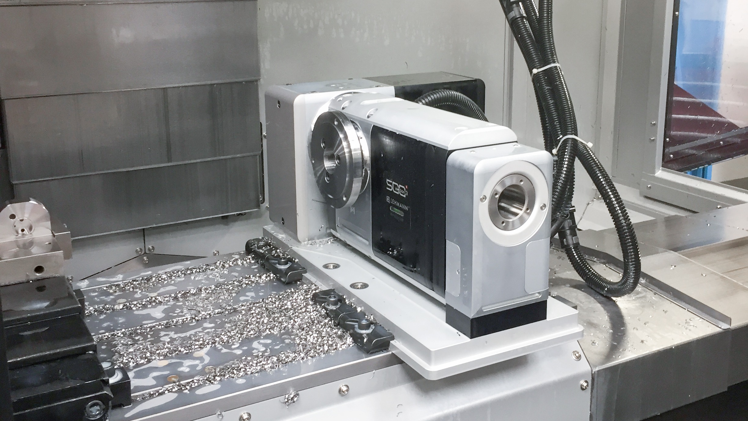
Take a pump flange with eight bolt holes and an oil groove that runs a third of the way round its rim. It's the kind of part where you choose between a worm gear rotary table and a roller cam table. The holes are drilled with the table locked at each angle. The groove is milled with the table turning as the tool feeds, and on the return pass the table reverses with the cutter still in the groove.
Both drives will drill the holes. The difference shows up on the groove. When the table reverses under load, the drive inside decides how far the groove edge shifts.
If most of your fourth-axis work is locked indexing, a worm gear rotary table with a good brake handles it, because the cut load goes into the brake. If you cut while the table turns, and the path reverses, a roller cam table's preloaded rollers leave less clearance to cross at each reversal. Direct-drive tables, with the motor built into the table, are a third option that this article doesn't cover.
| Worm gear table | Roller cam table | |
|---|---|---|
| Tooth contact | Sliding, between worm thread and wheel teeth | Rolling, between preloaded rollers and a cam rib |
| Clearance at reversal | Set by flank clearance; reduced by adjusting the worm | Taken up by roller preload |
| Over time | Wear opens the clearance; many designs allow re-adjustment | Makers claim little wear and no backlash adjustment |
| Locked cuts | Load goes into the brake | Load goes into the brake |
| Cutting while turning | Check reversal error and continuous output torque under load | Check reversal error and continuous output torque under load |
How a worm gear rotary table works, and where backlash comes from
The motor turns a worm, a screw-like shaft, and the worm turns a wheel bolted behind the table face. The worm thread slides across the wheel teeth, and there's a little clearance between the flanks.
When the drive reverses, the worm has to cross that clearance before it pushes on the opposite flank, and for that moment the table doesn't move. That pause is the backlash you see on a reversal check.
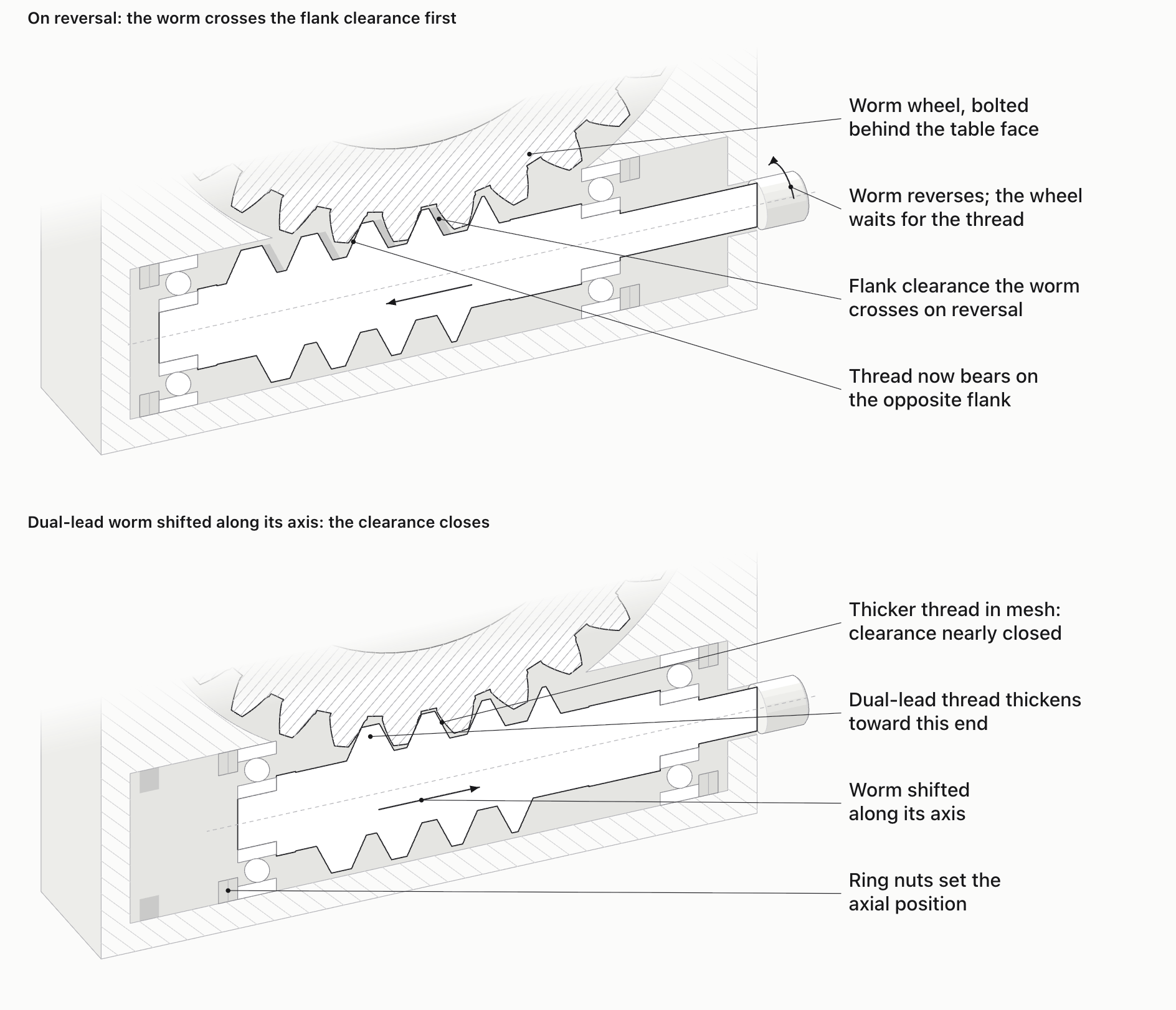
Many tables use a dual-lead worm, where the two flanks of the thread have slightly different leads, so the tooth gets thicker along the worm. Shifting the worm along its axis brings a thicker section into mesh and narrows the clearance.
This matters because sliding contact wears. As the flanks wear, the clearance opens again and the worm has to be re-set. Roller cam makers such as Sankyo and TJR put backlash adjustment on worm tables at once or twice a year. That's their comparison; the service manual of the table you're quoted is what counts.
Worm drives have real strengths. Makers such as Tsudakoma use full-depth tooth engagement and a larger module, and point to the contact area that gives as the reason their tables carry high torque. With the brake on, the cut load during locked indexing goes into the brake rather than the teeth.
How a roller cam takes up the gap a worm gear table leaves
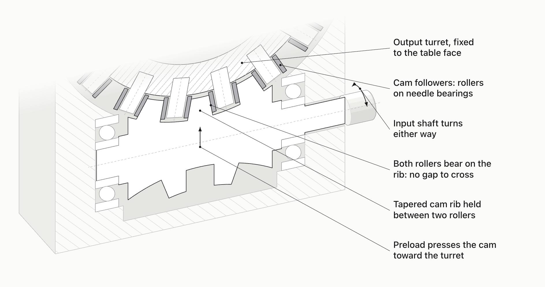
In a roller cam drive, the input shaft carries a cam with a tapered rib, and the output turret has a ring of rollers, called cam followers, round its rim. The rib sits between two rollers that press on it from both sides with preload. When the shaft reverses, the opposite roller is already in contact, so there's no clearance to cross. The rollers roll on the rib instead of sliding.
Makers of these tables, such as Sankyo and TJR, claim zero backlash and little wear. TJR adds that the drive needs no backlash adjustment, only oil changes, and quotes 20 arc-seconds indexing accuracy and 6 arc-seconds repeatability for its RC series, tested to ISO 230-2. These are makers' figures for their own series.
A 2009 study in the International Journal of Automation Technology, led by an engineer from the roller drive's maker, compared two test tables of the same size. The roller drive prototype gave better reversal and positioning readings, a higher natural frequency and smaller speed fluctuation at low speed.
Preload doesn't make the rest of the table rigid. Under a heavy cut, the bearings, housing and fixture still deflect, so a roller cam table should still be checked at the load you'll actually cut with.
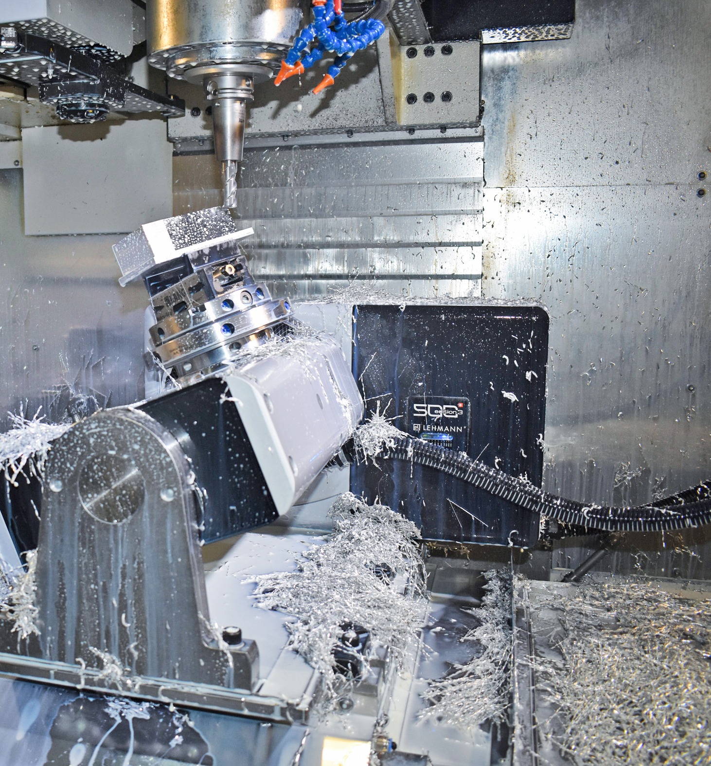
Locked indexing and cutting on the move: worm gear or roller cam table
For locked indexing, the table turns, stops, and a pneumatic or hydraulic brake clamps it before the cut. The cut load then goes into the brake. Here backlash matters less than two other figures: the clamped holding torque compared with the torque the cut puts on the table at its radius, and the time from the index command to the start of the next cut, including clamping and unclamping.
Table makers such as Kitagawa list clamping torque separately from servo holding torque, and both describe a table that's standing still. Use the clamping torque to check the cut on a locked table.
When you cut while the table turns, the brake is off, and the drive holds the position. Now backlash and drive stiffness show up on the part, at every point where the path reverses. Check the continuous output torque at the speed and duty you'll run, because the clamped torque doesn't apply here.
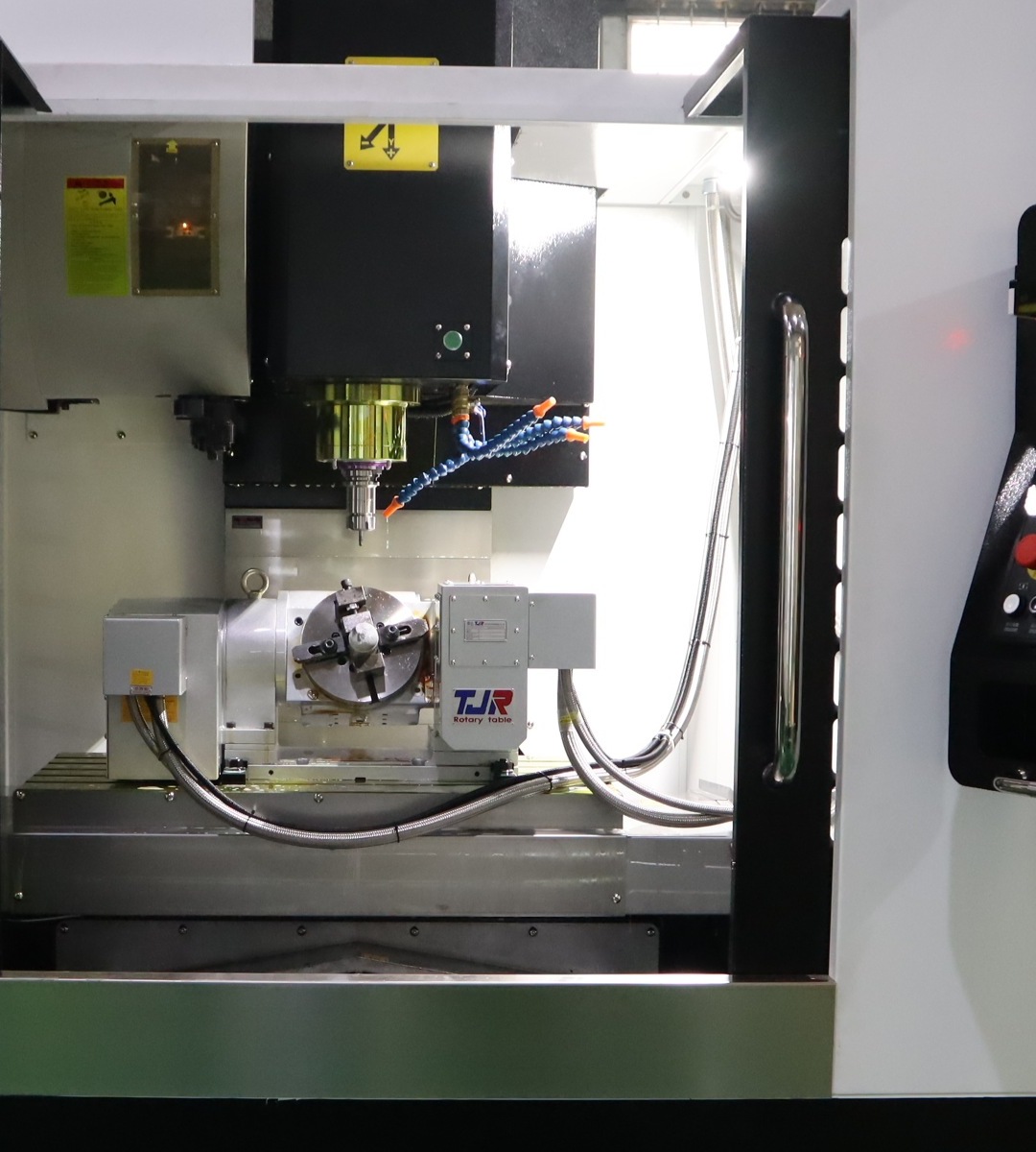
Time the index with your own fixture and a real blank on the table. An off-center load needs more torque to start and stop, so a table that's quick when empty can be slower on your setup, and a table with a lower catalog speed can come out ahead.
Four readings to keep apart on a rotary table
Backlash is the lost motion when the drive reverses. Indexing accuracy is how close the table stops to the commanded angle. Resolution is the smallest step the encoder or control can show. Part error adds the fixture, tool and the rest of the machine. ISO 230-2 tests positioning in both directions, so a bidirectional figure tells you more than a one-way one. A fine display step doesn't tell you much about the hole you'll measure on the bench.
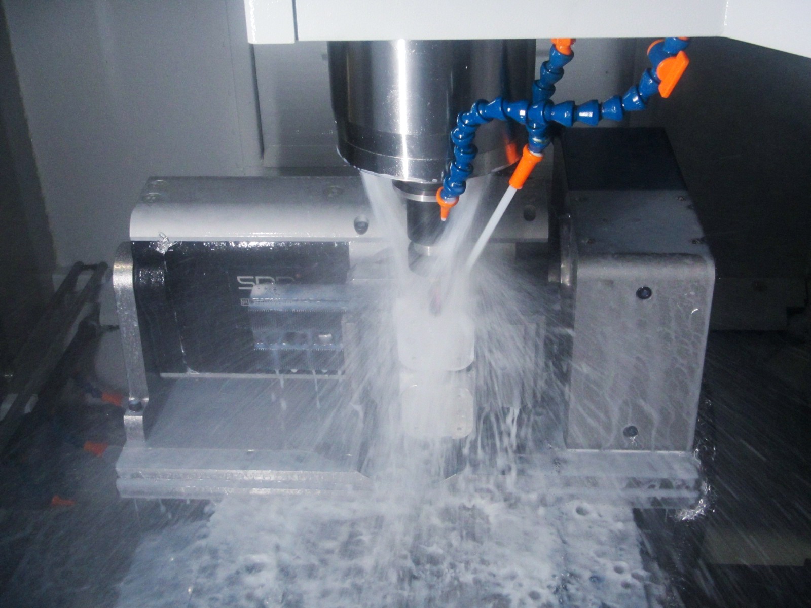
Worm gear or roller cam table: check your parts
- Are the cuts made at fixed angles, or does the table turn during the cut? For fixed angles, compare clamped holding torque and the full loaded index time.
- Does the path reverse while cutting? If so, cut a test feature in both directions and measure it from the same datum.
- Is the job a long repeat run? Ask how backlash is adjusted on the worm table you're quoted, how often, and how long the machine is down for it.
- Does the part need a tailstock? Include it, the fixture and the blank in the clearance and load check.
Before you compare drives, our fourth-axis sizing guide covers table size, fixture clearance and compatibility.
How we set up a fourth axis
On our vertical machining centers and drill-tap centers, we fit both drive types. Our worm gear rotary tables run from 125 mm to 630 mm in table diameter, including versions with an alloy-steel worm wheel up to 320 mm. Roller cam tables run from 170 mm to 320 mm. Each comes with a pneumatic or hydraulic brake for locked cuts.
For a part like the pump flange, we'd pick the drive from how much of the work is cut while turning, then size the table, tailstock and L-block to the part and the machine's travel, and check clearance with your fixture.
Send a part drawing and fixture details with the index angles and any cuts made while the table turns. We'll review the requirements, recommend a configuration, estimate the cycle time and prepare a quote.
FAQ
Can a reversal check tell me the error on the finished part?
It shows the lost motion of the table in the setup you measured. To see what reaches the part, cut a representative feature in both directions and measure it, so the tool and fixture are included.
Can I use the brake's holding torque as the rating for cutting while turning?
No. Holding torque applies when the brake is clamped and the table is stopped. When the table turns during the cut, check the continuous output torque at your speed and duty.
Does an alloy-steel worm wheel remove the need for adjustment?
The wheel material changes how fast the flanks wear, but the contact is still sliding. Follow the adjustment schedule for the table you buy.
Sources
- ISO 230-2:2014, positioning accuracy and repeatability of numerically controlled axes
- KHK Gears, worm gears technical guide: duplex worm and backlash adjustment
- Koma Precision, Tsudakoma technical features: full-depth tooth engagement and contact area
- Sankyo RollerDrive catalogue: theory of operation, preload and comparison with worm tables
- TJR, Roller Drive technology page: RC series data and comparison with worm tables
- Dassanayake and Tsutsumi, High Performance Rotary Table for Machine Tool Applications, International Journal of Automation Technology, 2009
- Kitagawa RK201 specifications: clamping torque and servo holding torque