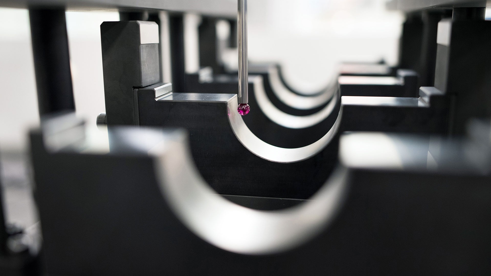
A shop installed a new horizontal machining center, and the first test part came off with a poor finish and dimensions out of tolerance. Suspecting the floor, they had the slab under the machine redone. The next cut came out exactly the same. In this case, the problem went away once the CAM settings were corrected. New CNC machine accuracy wasn't the cause.
Error on a first part that misses the drawing can come from four places, often more than one at once: how it was measured, what the program told the machine to do, how the tool and part sat during the cut, and how the machine itself moved. Only the last one is new CNC machine accuracy. Each source tends to leave a different pattern on the part, and that pattern is a clue to where to look first.
| Error source | Clue on the part | First check |
|---|---|---|
| Measurement | The reading changes when the part is re-seated or left to cool | Datum contact, burrs, gauge setup and temperature |
| Program | The same corner or profile is wrong on every part | Posted program version, tolerances and offsets |
| Tool and clamping | The error moves when you change a tool, clamp or part orientation | Change that one input and cut again |
| Machine geometry | The error stays at the same machine position across parts, tools and fixtures | Level and geometry check |
Measurement: new CNC machine accuracy starts with the reading
Unless the drawing says otherwise, dimensions are specified at 20 °C. Metal grows with temperature, aluminum by about 23 µm per meter for each degree. If the whole part is 5 °C above 20 °C and the reading isn't temperature-compensated, a 100 mm aluminum feature measures about 0.012 mm larger than it would at 20 °C.
A part fresh off the machine also cools unevenly, so while its temperature is still settling, a bore and a wall can change by different amounts.
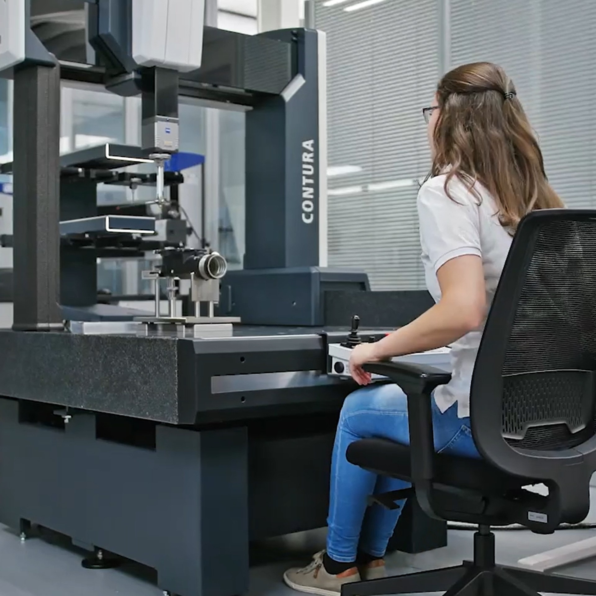
So pick one out-of-tolerance feature and measure it again with the datum, gauge and method the drawing calls for. Clean the contact faces, deburr the datum and note the part and gauge temperatures. If the number moves when you re-seat the part, the measurement setup is part of the problem; settle it before you change anything on the machine.
Program: errors the control was told to make
A machine cuts the path it receives, not the model on the screen. In some CAM systems, the tolerance used to calculate a toolpath and the tolerance used to smooth it add together. A corner can end up further from the model than either setting suggests, and it tends to land there on every part, which is a clue.
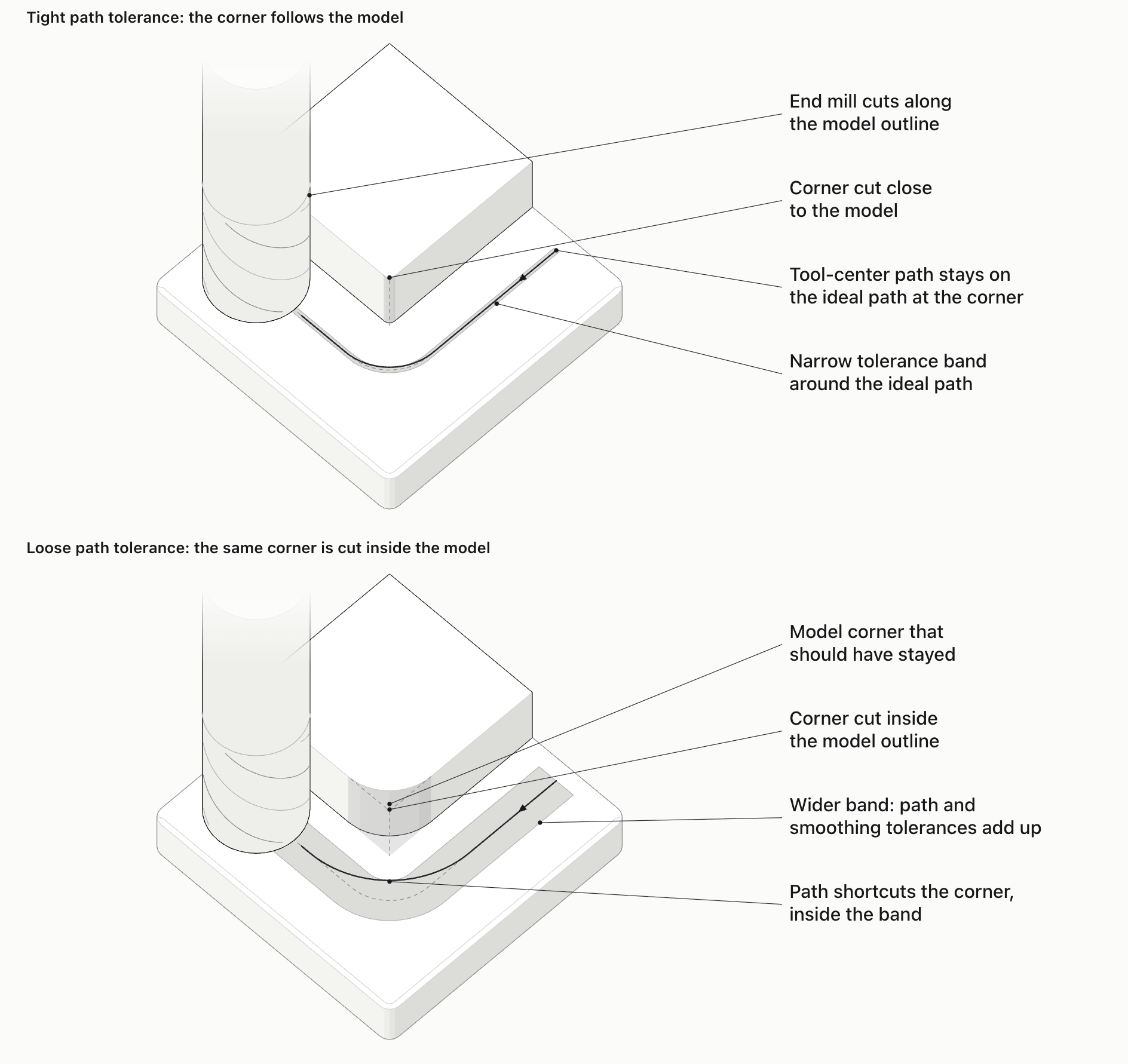
Compare the program version on the machine with the one you meant to post, and check the active work offset and tool offsets. Then test the two kinds of setting separately. For a CAM change, recalculate and post a new program, and keep both versions with their measurements. For a control setting such as the contour or smoothing mode, run the same NC file and change only that setting. Hold the tool, workholding and inspection the same in both.
Tool and clamping: errors that follow the setup
A chip or a burr in the spindle taper tilts the holder, and the tilt grows into runout at the cutting end. Measure runout on the tool assembly close to where it cuts, with the machine stopped and safe, and try a known-good holder at the same stick-out before you touch any machine compensation. For small cutters, our toolholder runout guide shows where to measure.
Clamping works on the part itself. A thin wall clamped outside its support bends under the clamp, gets machined flat in that bent state, and springs back when you release it.
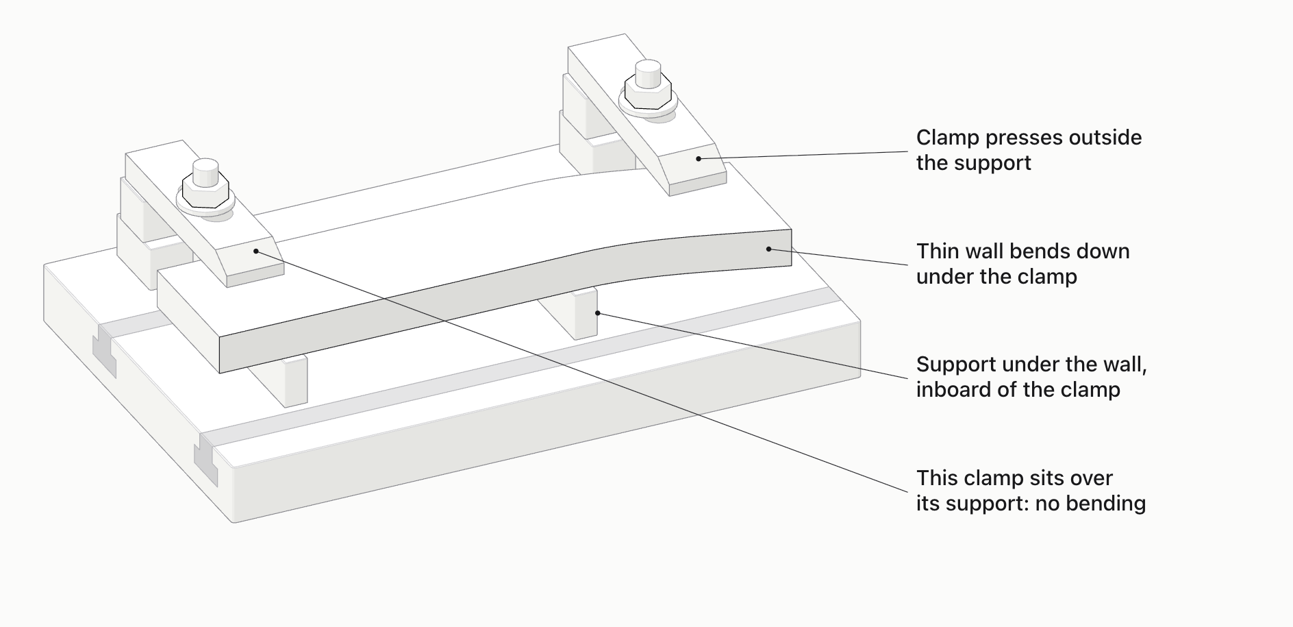
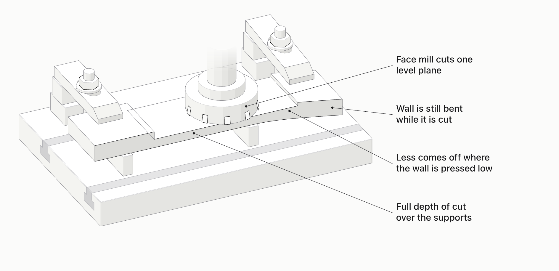
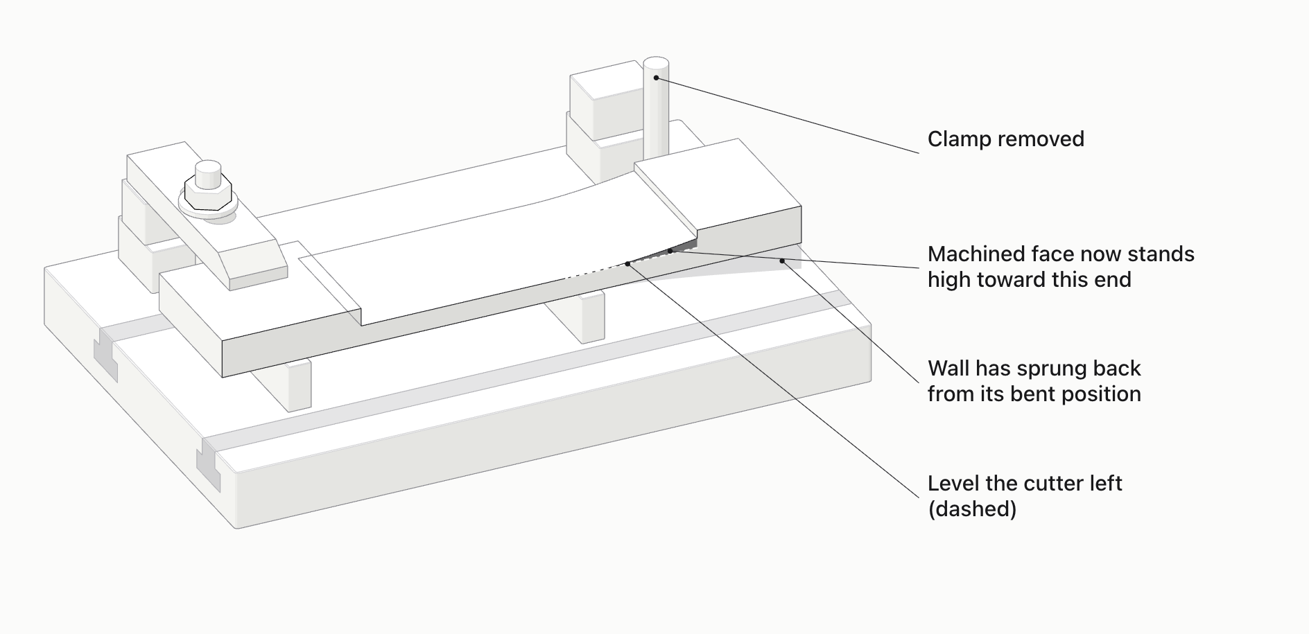
Measure the same feature clamped and unclamped, the same way. If the error shows up only after release, change the clamping before the toolpath.
Machine geometry: the part that is new CNC machine accuracy
When the same error repeats at the same machine position across different parts, tools and fixtures, the machine's motion is worth checking with independent instruments. Ask the installer or service team to check level and geometry, and give them your measurements and the program versions you've tried. If installation acceptance isn't finished, a leveling foot has moved, or there's been a collision or abnormal vibration, deal with that first.
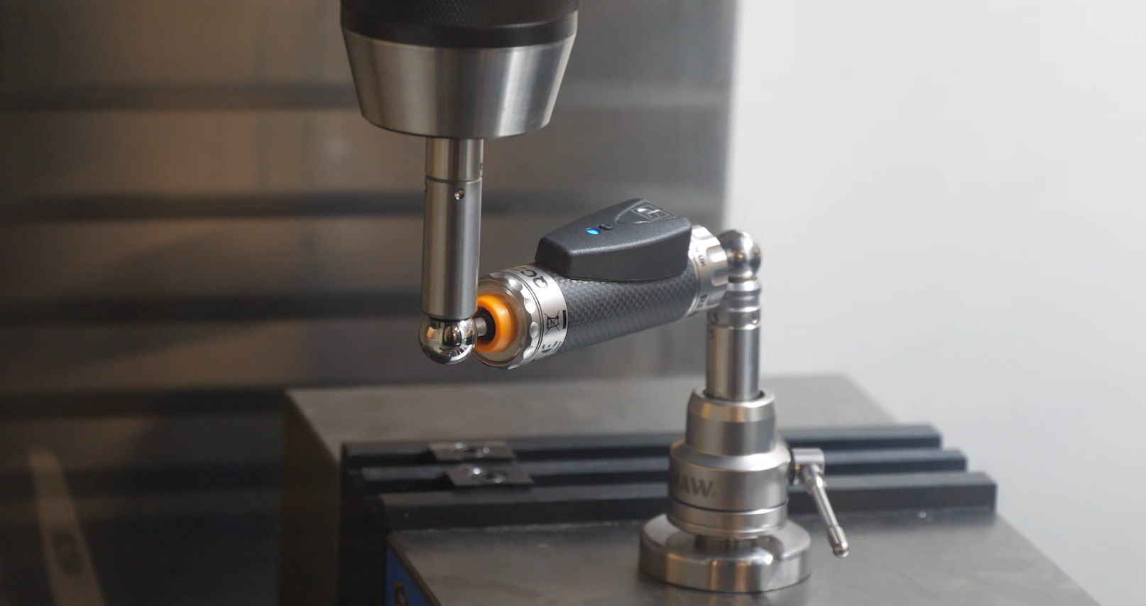
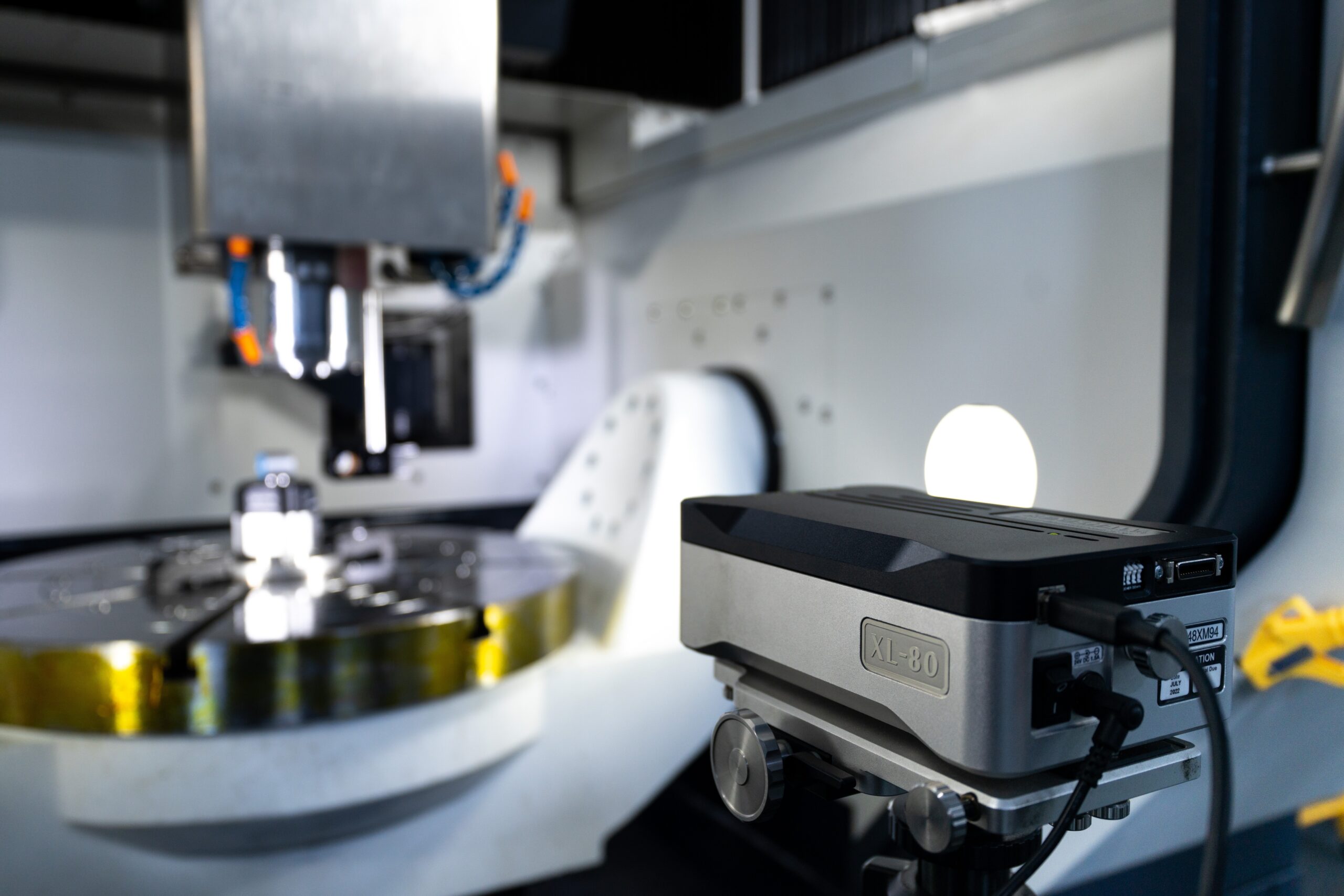
A ballbar records how closely the axes follow a programmed circle, and a laser interferometer checks how a linear axis positions along its travel. Both take the tool and fixture out of the result.
Heat matters here as well: a ballscrew that warms up during a run grows, and depending on the machine's position feedback and compensation, the axis positions can drift. Note how long the machine had been running when the part was cut. Then compare the deviations the tests find with the position and direction of the error on your part.
Keep the evidence from the first part
The shop with the new floor spent its time on the slab first. Keep one reference part with known critical features and the program that cut it, and record the program version and offsets for every part after it. When a result changes, you can narrow it down to the inputs that changed, then test them one at a time.
What we check for new CNC machine accuracy before shipping
At Chansin CNC, every machine runs continuously for 72 hours, is checked with a laser interferometer and makes a test cut before it ships. If you're planning a first-part check to confirm new CNC machine accuracy, bring the critical drawing features and how you'll measure them to a configuration discussion.
Sources
- Autodesk Fusion, toolpath tolerance and smoothing
- NIST, the 20 °C standard reference temperature, unless otherwise specified
- Renishaw, ballbar testing of circular motion
- Engineering ToolBox, linear thermal expansion coefficients of metals
- Renishaw, the effect of heat on ballscrew accuracy
The 5 °C and 100 mm figures are an illustration; the expansion rate is a typical value for aluminum alloys.