There is no universal runout limit for every small end mill. Runout becomes too much when it redistributes the intended chip thickness so severely that one flute carries most of the cut while another barely engages. The useful number is therefore not the toolholder specification by itself. It is the total indicated runout of the assembled spindle, holder, collet and tool, measured near the actual cutting position and judged against the tool diameter, programmed feed per tooth and the failure you are trying to explain.
This matters most with small cutters because their chip loads are small. A runout value that has little practical effect on a large roughing tool can consume a substantial share of the intended chip thickness on a miniature end mill. The result may appear as one damaged flute, early breakage, an oversized slot or a finish that changes after every tool change.
Why small end mills amplify the effect of runout
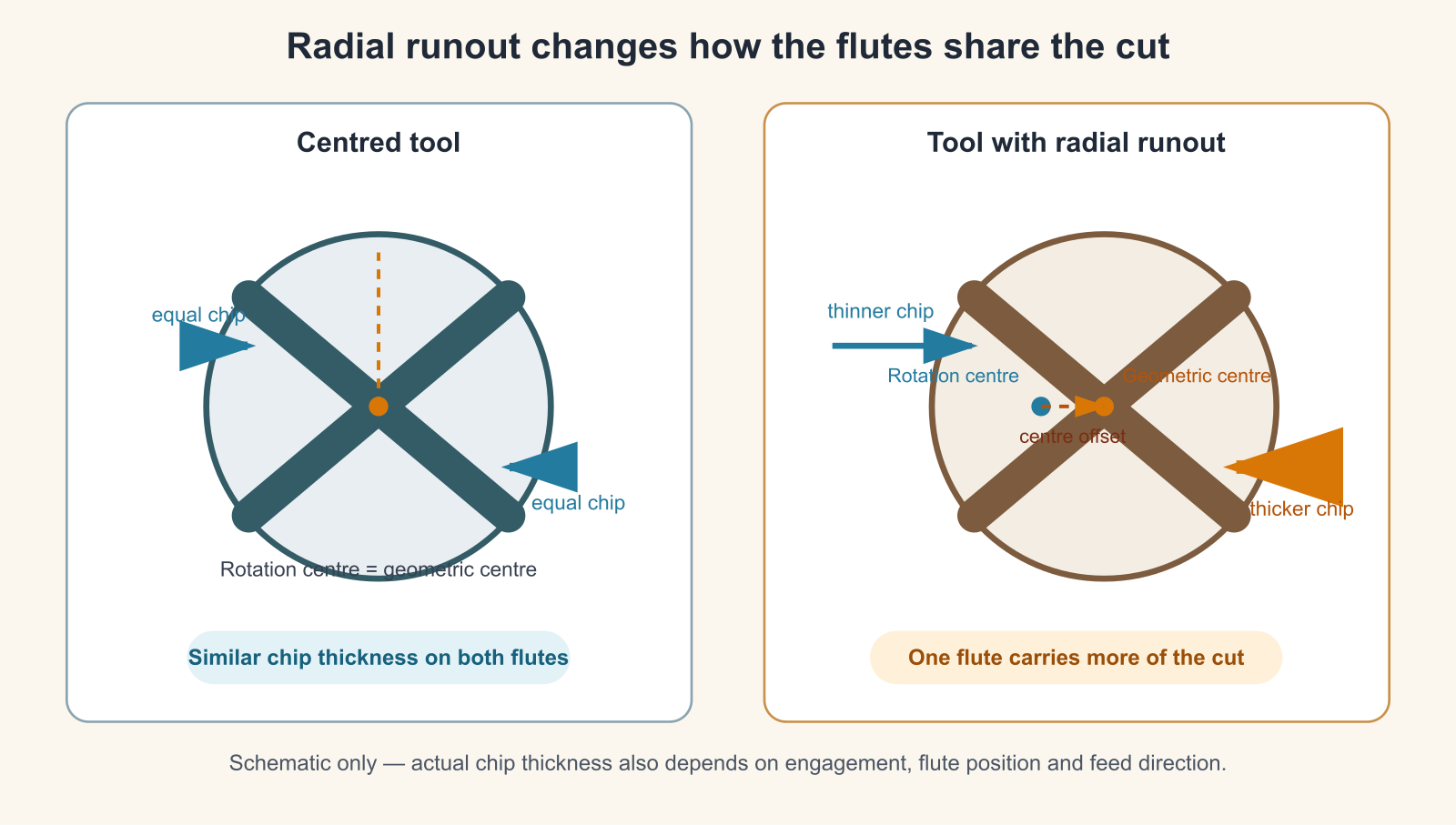
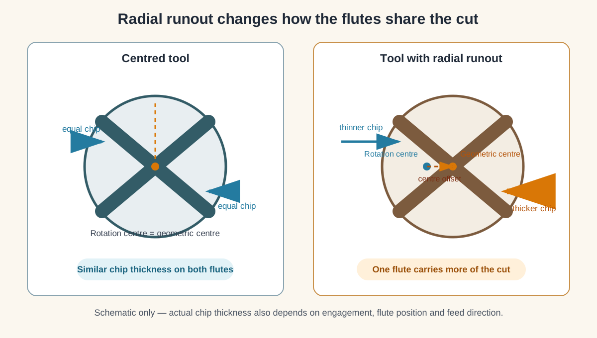
In an ideal two-flute cut, both edges remove similar chips. Radial runout shifts one edge farther from the axis of rotation. That edge enters the material more deeply, while the opposite edge removes less material. The programmed feed per tooth has not changed, but the actual load carried by each flute has.
Research on end milling has linked cutter runout with periodic differences in chip load and force, premature edge failure, surface-location error and roughness. Micro-milling research makes the scale problem especially clear: when tool diameter and intended chip thickness shrink, several micrometres of eccentricity can materially change which edge cuts. Those studies do not establish one allowable value for every shop. They show why runout must be judged relative to the cut.
The effect is not captured by simply subtracting the full TIR from the programmed feed per tooth. Actual chip thickness also depends on the number and angular position of the flutes, radial engagement, feed direction and the phase of the eccentricity. The ratio is still useful as a warning: when measured runout is no longer small compared with the intended chip thickness, equal flute loading should not be assumed.
“Toolholder runout” is usually a stack of errors
A reading taken on the cutting tool contains more than the holder’s manufacturing tolerance. The spindle taper, holder taper, collet, nut, cutting-tool shank, dirt between mating surfaces and the way the assembly was tightened can all move the tool away from the spindle axis. Tool geometry can add another component if the cutting diameter is not perfectly concentric with the shank.
Stickout changes what you see. If the tool axis is slightly tilted, a reading close to the holder may look acceptable while the error grows toward the cutting edge. A holder can also repeat differently after it is removed and reinstalled. One reading at one axial position cannot separate these causes.
Measure at more than one point
Start with clean, undamaged contact surfaces and a spindle in the thermal condition normally used for the job. Rotate the spindle slowly by hand where the machine design and safety procedure allow it. Do not run the spindle against a contact indicator. For fragile miniature tools, a non-contact measuring system may be more appropriate because indicator force and flute geometry can distort the result.
| Measurement | What it helps isolate | Important limitation |
|---|---|---|
| Spindle taper or qualified spindle test surface | Spindle-side geometric error or contamination | Does not include the holder, collet or cutting tool |
| Precision test bar in the holder | Holder and clamping-system contribution | Depends on the test bar and assembly method |
| Tool shank close to the holder | Assembled-system repeatability near the clamp | May hide angular error that grows with stickout |
| Near the cutting position | The error most relevant to the actual cut | Flutes complicate contact measurement; static TIR does not capture every high-speed effect |
Measure the assembly more than once. Remove and reinstall the holder, then repeat the reading. Re-clamp the tool and repeat. If the value or high point moves substantially, the problem may be seating, contamination, collet condition, tightening practice or component interaction rather than one permanently eccentric part.
How to decide whether the measured runout is too much
Use three tests together.
One manufacturer-specific value can serve as a screening reference. In Union Tool’s September 2023 CBN-LRF four-flute long-neck radius end-mill leaflet, the safety guidance recommends a runout control value of 5 µm or less for small-diameter tools of 1 mm or below on a rigid, low-vibration machine. The same guidance says final cutting conditions may need adjustment for the work material, milling shape and strategy, machine rigidity and spindle capability. The 5 µm figure is therefore a screening line within that tool-family guidance, not a universal allowable TIR for every small end mill or setup.
1. Compare runout with the scale of the cut
Consider tool diameter and intended feed per tooth, not diameter alone. A finishing pass with a very small chip thickness may be sensitive even when the cutter is not a micro tool. If the TIR is a meaningful fraction of the intended chip thickness, expect the flutes to share the cut unevenly. Use the tool manufacturer’s runout guidance where it exists; do not replace it with a rule copied from a different tool family.
2. Look for flute-to-flute evidence
Inspect every cutting edge under suitable magnification. One heavily worn or chipped flute while the others remain comparatively fresh is stronger evidence than a runout number viewed alone. Uneven chip color, a once-per-revolution force pattern, slot-width error and a repeating surface mark can support the same diagnosis. They can also have other causes, so the evidence should agree before changing the entire tooling system.
3. Check whether the result follows the assembly
Re-seat the holder, rotate or replace the collet where the system allows, use a known test bar, and compare another pocket or spindle position only if the machine architecture makes that comparison valid. If both TIR and cutting behavior improve after one controlled change, the suspected source becomes more credible. If cutting behavior remains poor after the runout improves, return to chip thickness, toolpath, rigidity, workholding, material and coolant.
A practical troubleshooting order
- Clean and inspect. Remove chips, fretting residue and damage from the spindle taper, holder, collet, nut and tool shank. A small particle between precision surfaces can tilt the assembly.
- Reassemble consistently. Use the correct collet range, insertion depth and tightening method. Avoid clamping on a transition, flute or damaged shank.
- Reduce unnecessary stickout. Keep enough clearance for the cut, but do not extend the tool farther than the geometry requires.
- Measure the holder with a test bar. This helps distinguish cutting-tool geometry from the holder and spindle stack.
- Substitute one known component. Change only the collet, holder or tool so the result remains interpretable.
- Check repeatability after tool changes. A low reading that cannot be reproduced is not a stable process condition. When sister tools are involved, treat each holder-tool pair as a qualified assembly; the same physical-versus-logical distinction also matters when calculating tool-magazine capacity.
Do not begin by changing the holder specification or by lowering feed until the tool survives. Lowering the programmed chip thickness can make the runout-to-chip-thickness relationship worse, while a more precise holder cannot correct a dirty taper, damaged collet or poorly ground tool.
Static TIR and cutting behaviour can diverge
A hand-rotated indicator reading is a geometric check. At cutting speed, spindle error motion, thermal growth, toolholder imbalance and tool bending under force can change the effective path of the edges. Research on dynamic runout shows that the cutting process can differ from the static condition, especially at high rotational speed and small scale.
This does not make static measurement useless. It makes its role specific: static TIR is a fast way to find assembly and geometric problems. If static runout is low but the same flute still carries most of the wear, the next test should examine dynamic behavior, engagement, tool deflection and spindle condition rather than chasing a smaller static number.
The runout limit belongs to the assembled process
For a small end mill, runout is too much when the assembled system no longer lets the flutes share the intended cut without unacceptable wear, breakage or geometry error. Measure close to the cutting position, repeat the assembly, and relate the result to feed per tooth, tool diameter and flute-level evidence.
The practical target is not zero on one indicator reading. It is a repeatable tool path that stays within the selected tool’s guidance and produces balanced wear under the actual engagement. Static TIR can identify an important part of that problem, but it cannot replace a cutting test or explain every failure by itself.
Sources and Method
- Tony L. Schmitz and co-authors, “Runout Effects in Milling: Surface Finish, Surface Location Error, and Stability,” 2007 — experimental and modelling evidence on tooth runout, cutting load, surface error and stability.
- “Tool Run-Out Measurement in Micro Milling,” Micromachines, 2017 — scale-specific evidence on runout measurement and its effect on micro-milling forces, tool life and surface integrity.
- “Improvement of Machining Accuracy by Measurement and Adjustment of Dynamic Runout of End Mill,” Procedia CIRP, 2021 — small-diameter end-mill evidence on dynamic runout and machining performance.
- Harvey Performance, “Reducing Tool Runout” — manufacturer guidance on measurement position, system contributors and miniature-tool measurement.
- Union Tool, “CBN-LRF 4 Flute High-Grade Long Neck Radius End Mills,” September 2023 — product-family guidance for the 5 µm screening value, diameter boundary and machine-condition limits stated in the article.
The measurement sequence combines published runout mechanisms with practical checks of the assembled spindle-holder-tool system. The Union Tool value remains confined to the product-family conditions stated above.