When a single-spindle lathe makes long, stringy chips during external finishing, identify the cut that makes them before changing coolant pressure or buying a different insert. Record the material, insert designation and edge condition, programmed feed and depth of cut, and the surface result. Then compare that cut with the chip-control area published for the actual insert geometry. If it lies outside the recommended area, a controlled change to one variable or a more suitable geometry may be justified. If it lies inside, look for wear, material variation, coolant delivery or an interrupted chip path. A chipbreaker does not have one universal feed threshold.
Find the cut that makes the stringer
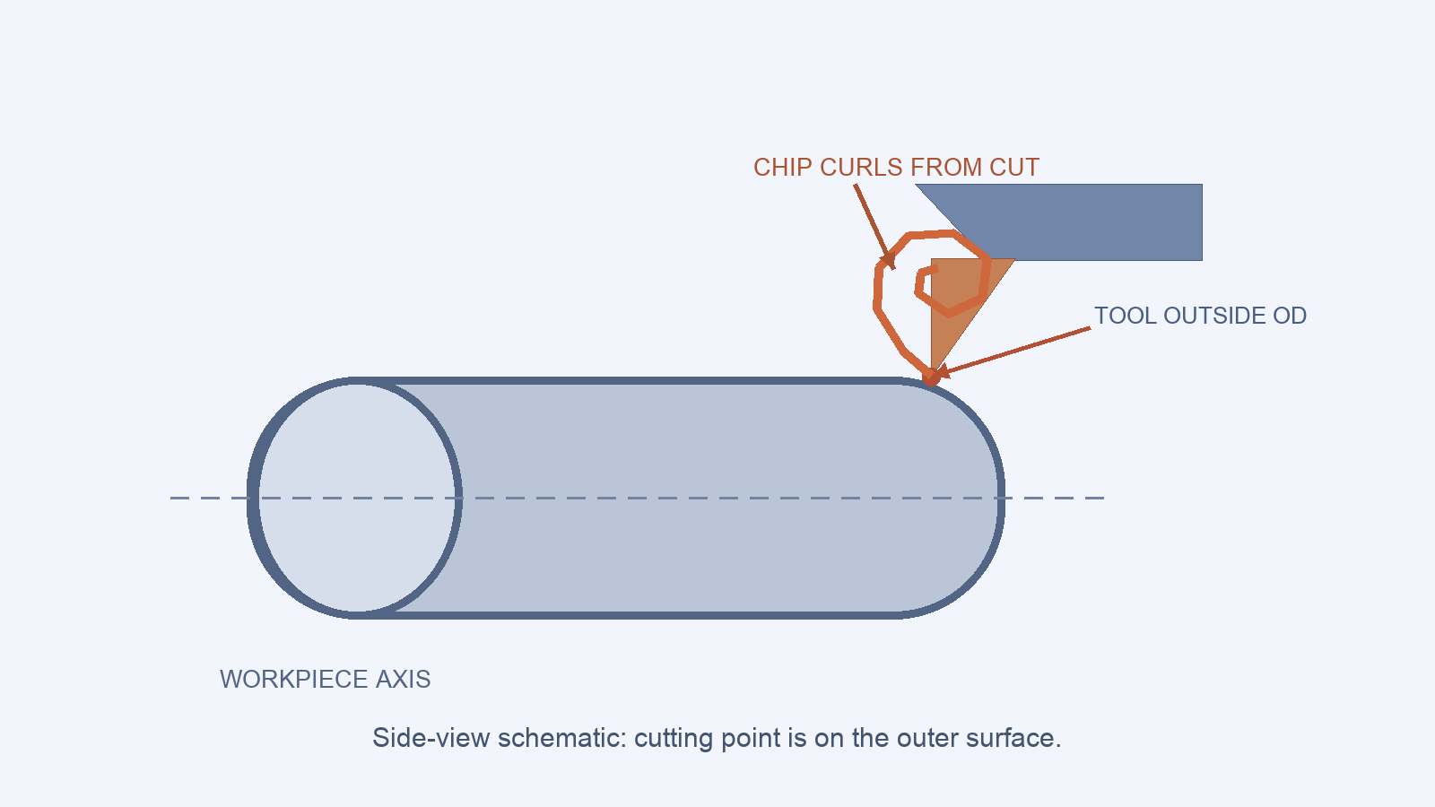
“The machine makes long chips” is too broad a fault description. Watch a safe, enclosed cycle or use the collected chips and program to identify the operation: a light finishing pass, a taper, a facing cut or a roughing cut may place the same insert in very different conditions. A multi-spindle chip-tangling discussion covers another operating context; here the first task is to locate the single-spindle pass producing the stringer. Note whether the problem began with a new material batch, a tool change or an edited program. Keep the workpiece surface and size on the same record; shortening chips is not a success if the part then fails its drawing.
If chips have wrapped around the tool or workpiece, stop and follow the machine’s lockout and chip-removal procedure. Do not reach into a moving machine or use a trial cut to “clear” a hazardous bundle. The diagnostic sequence begins only after the immediate obstruction is handled safely.
Read the insert’s chip-control area
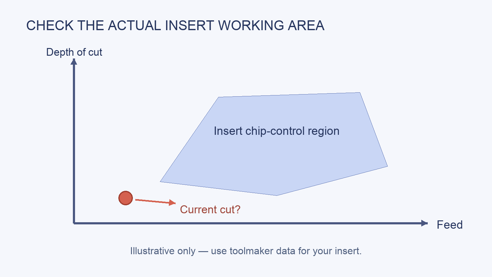
Turning chipbreaker geometry is chosen for a range of chip thickness and engagement. Toolmakers commonly show that range using feed and depth of cut for a particular geometry and work material. A Sandvik Coromant explanation of finish, medium and roughing geometries demonstrates why a roughing geometry may not form chips well in a light finishing cut. The relevant chart is the one for the insert actually in the turret, not a generic chart remembered from another job.
Find the manufacturer’s insert code, geometry designation, recommended material group and feed/depth region. Mark the current cut on that chart. If the point falls outside it, first decide whether a different insert geometry is appropriate for the required surface and size. Changing feed or depth solely to improve chip shape may be impossible on the final pass. If the point falls inside the published region, inspect the cutting edge and confirm the programmed cut is actually being taken. A worn edge or a very small remaining stock allowance can change chip formation from what the program suggests.
Change one thing and keep the evidence
When a safe trial is possible, change one process variable at a time and collect a short comparison of chip shape, surface finish and size. A Seco Tools discussion of chip challenges maps feed, depth and insert geometry against chip shape and cutting force. That is a useful diagnostic direction, but it does not mean “always increase feed.” A higher feed can conflict with finish, tolerance, tool load or the geometry’s own range.
Suppose the stringer appears only on a light final pass. If the finishing insert’s chart shows the programmed cut below its effective chip-control region, compare a suitable finishing geometry with a permitted adjustment to stock allowance. Test under the same material and coolant conditions. If the new chip is shorter but the finish deteriorates, the change has not solved the complete problem.
| Observation | Next check | Why it matters |
|---|---|---|
| Only one finishing pass makes long chips | Its actual depth and insert chip-control area | A light cut may miss the geometry’s intended range. |
| Problem began after an insert change | Full insert code and geometry, not only grade | Different chipbreakers can behave differently in the same material. |
| Same programmed cut now behaves differently | Edge wear, stock variation and material lot | The actual engagement may have changed. |
| Chips break but accumulate around the part | Coolant direction and evacuation path | Chip formation and chip removal are different problems. |
When to investigate coolant or the machine
Coolant position and chip evacuation matter after you know whether chips are being formed long or are merely collecting. A directed jet may move chips away while leaving their formation unchanged. Similarly, a machine with better chip evacuation can reduce accumulation without making an unsuitable insert geometry suitable. Check nozzle direction, flow and enclosure limits against the machine and coolant-system instructions rather than adding pressure as an assumed cure.
If several tools and materials suddenly produce abnormal chips, widen the investigation to setup, coolant delivery and machine condition. If only one material and one cut are affected, stay close to that job’s insert, engagement and material. Any trial must stay within the actual insert maker’s range and the machine’s permitted operating limits.
Sources and method
The insert-region comparison draws on toolmaker guidance from Sandvik Coromant and Seco Tools.