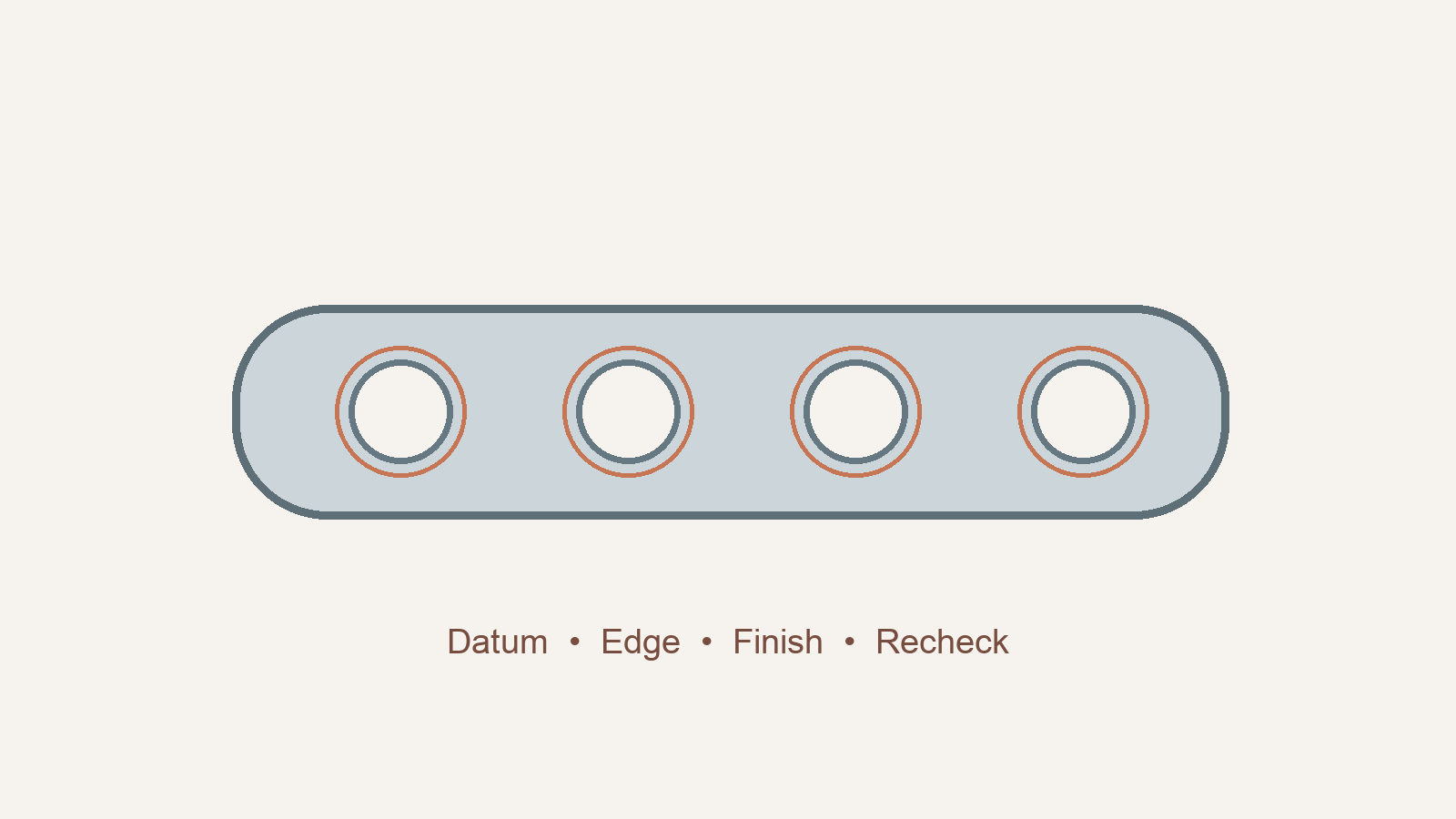
For a titanium bone plate prototype, treat each screw hole as a feature that must survive several operations, not as a diameter to check once after drilling. The process plan should identify the datum and support used to make the hole, inspect the entry and exit edges after cutting, then check the relevant geometry and edge condition again after deburring or other finishing. The drawing and approved inspection plan determine what is acceptable.
Translate the drawing into a hole-feature plan
Begin with the released drawing: locate every screw hole, its axis or positional requirement, the required edge form and any thread or countersink feature. Record which dimensions will be checked after machining and which must be rechecked after finishing. If an edge condition is called out only in a general note, clarify how it will be assessed before choosing a deburring method. “No visible burr” is not a substitute for an agreed inspection criterion when the customer has a specific requirement.
A plate may be thin, curved or locally flexible. The support used during cutting can therefore affect the reference from which a hole is made and inspected. Document the fixture contacts and the datum transfer between machining and inspection. The purpose is to expose a mismatch early: a hole can look clean at the machine while its measured position changes when the plate is released or held differently.
Inspect both edges, not only the tool exit
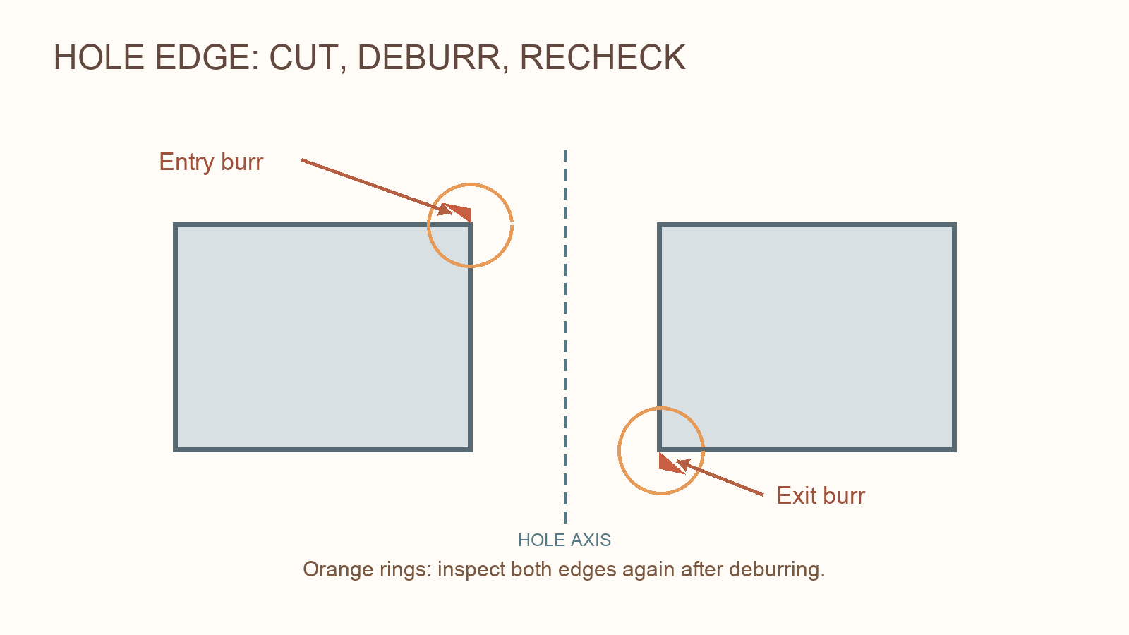
Drilling and subsequent deburring can leave different edge conditions. A published Ti-6Al-4V drilling experiment measured burrs at tool entry and exit and investigated secondary burrs after an integrated deburring operation. Its particular tool, flat specimen and test setup support checking more than one stage and edge on a prototype.
For a prototype, record a view of the hole entrance and exit after the cutting operation. Then note which edge is actually accessible to the selected finishing tool. A process that removes a visible exit burr may change a chamfer or create a small raised edge elsewhere. Check the resulting edge after the finishing pass, including any feature that the tool might have touched on withdrawal. If a hole is blind or its geometry differs from the example, choose inspection points from that drawing rather than applying a through-hole checklist unchanged.
Carry the hole through post-processing
One research study of additively manufactured tibial fixation-plate prototypes included finishing, optical inspection and later CNC machining of holes and threads. The small prototype set illustrates why the condition of a hole depends on when it is created relative to the other finishing steps.
For a machined plate, write the actual sequence on a feature card. Will surface finishing occur before the holes, after the holes, or on both sides of them? Can a polishing or blasting operation alter an edge, thread or datum used in inspection? If it can, plan a later check. If the approved route already controls that operation and demonstrates stable results, use its validated checkpoints.
Use a feature card during the first trial
| Stage | Record on the first article | Question before moving on |
|---|---|---|
| Setup | Drawing revision, hole identity, datums and support contacts | Will inspection locate the plate in a comparable way? |
| Hole machining | Tool and operation used; entry, exit and feature measurements | Is the observed edge condition within the agreed criterion? |
| Deburring or finishing | Method, contacted surfaces and edge appearance afterwards | Did the operation change the hole, chamfer or nearby surface? |
| Final inspection | Specified dimensions and edge checks against the approved plan | Is the finished feature acceptable, rather than only the cut feature? |
The card is most useful when it contains the actual drawing callouts and measurement method. It should not become a generic form that merely says “checked” at every stage. Where the feature cannot be measured reliably in the fixture, agree how it will be held and measured after release.
What the published examples do not establish
A separate patient-specific plate study used five-axis milling of a medical titanium alloy plate. By comparison, the site’s bone-screw Swiss-turning article follows a slender rotating screw. The plate’s hole edges and datums call for a different process and inspection plan.
Material grade, plate thickness, screw-hole geometry, finishing route and regulatory obligations remain specific to the product and its approved quality system. Resolve those inputs with the design and quality owners before setting acceptance criteria. The practical gain is that a clean-looking hole is checked at the right times and against the right feature definition.
Sources and method
The entry, exit and secondary burr discussion draws on the Ti-6Al-4V drilling experiment. The process sequence is informed by fixation-plate prototype research and a machined patient-specific plate study.