Answer first: In a high-removal-ratio monolithic aluminum rib or frame, material-removal sequence matters because each cut removes part of the blank’s residual-stress field while reducing the stiffness that resists the next release. The final free shape is therefore not controlled by cutting force alone. A reliable investigation must separate blank-initial residual stress, machining-induced stress, fixture constraint and thermal/tool effects by measuring the part at defined stages—especially after unclamping. Changing feeds and speeds before separating those sources can improve the wrong mechanism.
This article focuses on one problem: how can a process engineer test whether material-removal sequence is driving distortion in a thin-walled aerospace monolithic part? It does not claim that symmetric or alternating removal is always best, nor does it prescribe a universal wall thickness, alloy, stress-relief route or compensation value.
Why an accurate machine can produce a distorted free part
A rolled, stretched or forged blank can contain self-equilibrating residual stress before machining. While the blank is intact, tensile and compressive regions balance. Removing material changes that balance. The remaining body seeks a new equilibrium, and its geometry changes according to both the released stress and the stiffness of the remaining structure.
Machining adds other effects. Near-surface plastic deformation and heat can create machining-induced residual stress. Cutting and clamping forces elastically deflect thin walls. Thermal drift changes the relationship between tool, fixture and part. These mechanisms can coexist, but they leave different signatures.
Aurrekoetxea, López de Lacalle and Llanos describe aerospace monolithic-part distortion as a combination of blank-initial residual stress, machining-induced stress, thermal deformation, clamping and process forces. Their on-machine layer-removal work emphasizes that initial blank geometry and machining stress must be included when estimating bulk residual stress. Weber and colleagues separately modeled both initial and machining-induced stresses with the true milling path, then validated distortion predictions experimentally. In their particular low-initial-stress test pieces, changing only the milling path reduced distortion by 42% for a 3 mm wall; simulations indicated greater potential at 2 mm. Those percentages belong to the reported specimens, not to every aerospace part. The transferable conclusion is that path and sequence can matter enough to test directly.
Distortion is a state change, not a single inspection number
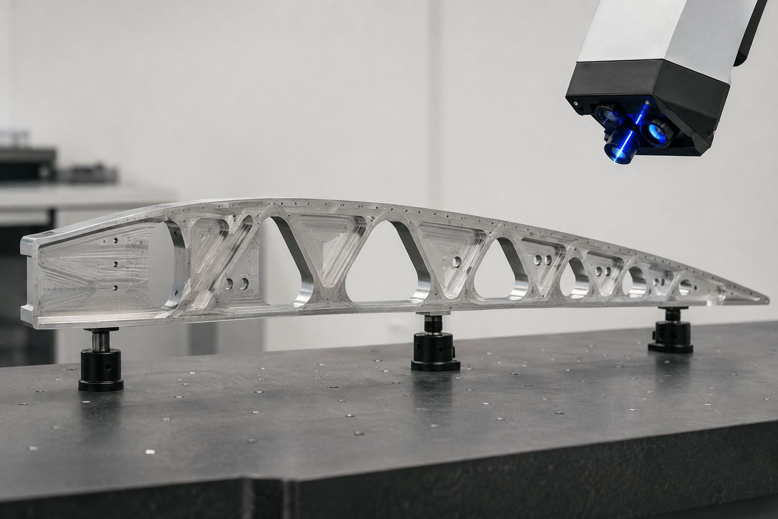
A part can be accurate while clamped and distorted when released. This is not necessarily a measurement contradiction. The fixture supplies forces that may flatten the part and temporarily balance released stress. Once the clamps open, the part moves to a new free-state equilibrium.
At minimum, keep four measurement states distinct:
| State | Measurement | Primary diagnostic value |
|---|---|---|
| S0: blank | Initial geometry, lot, orientation and any residual-stress characterization | Separates stock variation from process variation |
| S1: after roughing, clamped | In-process datums, stock distribution and temperature | Shows tool/fixture relationship under constraint |
| S2: after roughing, free | Free-state surface or point-cloud map after unclamping and defined soak | Exposes released stress and fixture springback |
| S3: finished, free | Final functional geometry at the specified inspection condition | Acceptance plus remaining process signature |
The most informative quantity is often a difference map rather than a pass/fail result. The change from S1 to S2 reveals what the fixture was holding. The change from S2 to S3 includes the effect of semi-finishing and finishing. If S0 varies strongly by blank lot and the final distortion direction follows that variation, stock is a stronger lever than a small feed adjustment.
Why one-sided and alternating removal can behave differently
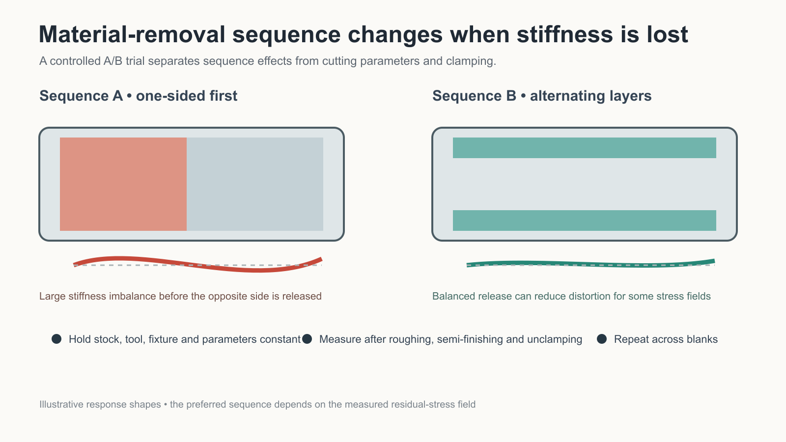
Imagine a plate whose through-thickness residual-stress profile is approximately balanced. Removing most stock from one face first destroys symmetry while the opposite face and its stress remain. The part may bend early, and subsequent cuts occur on a geometry already changed by release and constraint. Alternating layers can preserve balance longer—but if the actual stress field is not symmetric, an apparently symmetric sequence may still be wrong.
The mechanical relationship can be expressed schematically:
ufree = C(Gremaining) · F(σblank, σmachining, removed volume)
The free displacement u depends on released stress effects F and structural compliance C, which changes as geometry G is removed. This is not a closed-form prediction. It is a reminder that identical stress release can produce a larger displacement after ribs and webs have become thin.
Sequence also changes where and when machining-induced stress is introduced. A finishing pass on a compliant wall does not have the same mechanical boundary conditions as the same pass on a thick semi-finished wall. For this reason, “same tool and same parameter” does not guarantee the same residual effect at different stages.
A controlled A/B experiment for a new order
The objective is not to find a perfect sequence in one trial. It is to determine whether sequence is a material cause under the actual stock and geometry. Use representative blanks from the same lot and keep the following fixed: orientation in the plate, stock allowance, fixture, clamp force, cutter, tool life, cutting parameters, coolant, machine warm-up and measurement method.
Then compare two routes:
- Route A: the current or deliberately one-sided removal sequence;
- Route B: an alternating, symmetric or stiffness-preserving sequence designed from the same geometry.
Measure S0 through S3 and record the volume removed at each stage. Repeat parts in each route; one part per route cannot separate sequence from blank-to-blank stress variability. Randomize order where practical so machine temperature and tool wear do not align with one route.
Interpret the patterns, not only the final maximum
Several outcomes are possible:
- If Route B repeatedly reduces S1-to-S2 springback while S0 is similar, sequence is a credible lever.
- If both routes vary mainly by blank lot and retain similar distortion shapes, stock characterization or orientation deserves priority.
- If clamped measurements drift with temperature but free-state maps recover after soak, thermal control is dominant.
- If a specific wall bends during the finishing pass and the effect follows tool condition, cutting force or machining-induced stress may dominate locally.
- If low-force free-state measurements disagree by support orientation, the measurement system is not yet capable of resolving the process.
A shape map adds causal information that a single flatness value loses. Twist, global bow, local wall pull-in and datum rotation point to different mechanisms. Preserve common alignment rules so registration does not mathematically remove the deformation being investigated.
Separate four causes before selecting a remedy
| Hypothesis | Expected signature | Useful challenge | Likely lever |
|---|---|---|---|
| Blank residual stress | Lot/orientation dependence; progressive release with depth | Layer-removal characterization or paired blank study | Stock route, orientation, allowance or preconditioning |
| Machining-induced stress / force | Surface/process dependence; local wall response | Tool/parameter factorial test with stable stock | Tool geometry, parameters, finishing strategy |
| Fixture constraint | Large S1-to-S2 change; clamp-force sensitivity | Clamp-force ladder and alternative support | Locator/support layout and force control |
| Thermal / tool drift | Time, temperature or tool-life dependence | Warm-up, soak and tool-life blocks | Thermal discipline, wear compensation, timing |
The remedies are not interchangeable. Tool-path compensation may make one known distortion field dimensionally correct, but it can fail when the next blank has a different stress profile. Lower clamp force may expose the real shape but reduce stability. Intermediate stress relief may reduce one mechanism while adding time, oxidation or requalification burden. The correct action follows the dominant signature and production economics.
When sequence optimization has limited value
Sequence is less important when the blank is demonstrably low-stress, the removal ratio is low, the remaining structure is thick and symmetric, or the observed error is dominated by a fixture or thermal issue. It is also possible for a sequence that minimizes free-state distortion to increase cycle time, tool travel or setup complexity. The best industrial route balances geometry, repeatability and cost rather than minimizing a single displacement at any price.
Simulation can reduce experiments, but it needs credible initial stress, machining stress, material and boundary conditions. A model calibrated to one blank lot may provide false confidence on another. Experimental checkpoints should remain until prediction error is understood across the process range.
Engineering conclusion
Material-removal sequence is a hypothesis to test, not a universal cure. The decisive evidence is a controlled comparison across repeated blanks with stagewise free-state measurements. That experiment reveals whether geometry moves when stress is released, when stiffness is lost, when clamps are removed or when the tool and temperature change.
For a new monolithic-part order, preserve the blank history, define measurement states before cutting, and use the distortion pattern to select the next experiment. If sequence is causal, redesign it around balanced stress release and remaining stiffness. If it is not, stop tuning the tool path and move to the stock, fixture, thermal or cutting mechanism supported by evidence.
Sources and Method
- Weber et al., “Simulation Based Compensation Techniques to Minimize Distortion of Thin-Walled Monolithic Aluminum Parts Due to Residual Stresses,” 2022 — experimental and model evidence on residual stress, true milling paths and wall thickness.
- SAE, “Control of Machining Distortion in Aluminum Airframe Components,” 2005 — aerospace industrial context for layer removal and distortion control.
- Aurrekoetxea, López de Lacalle and Llanos, “Machining Stresses and Initial Geometry on Bulk Residual Stresses Characterization by On-Machine Layer Removal,” 2020 — coupled-source and layer-removal measurement method.
- “On-machine Characterization of Bulk Residual Stresses on Machining Blanks,” 2019 — shop-floor residual-stress characterization for ribbed aluminum structural parts.
The four-source diagnostic matrix and A/B sequence experiment are original engineering syntheses. Reported improvement percentages remain attached to their source specimens and are not presented as a production guarantee.