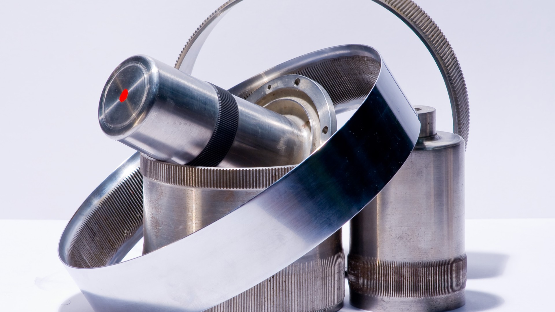
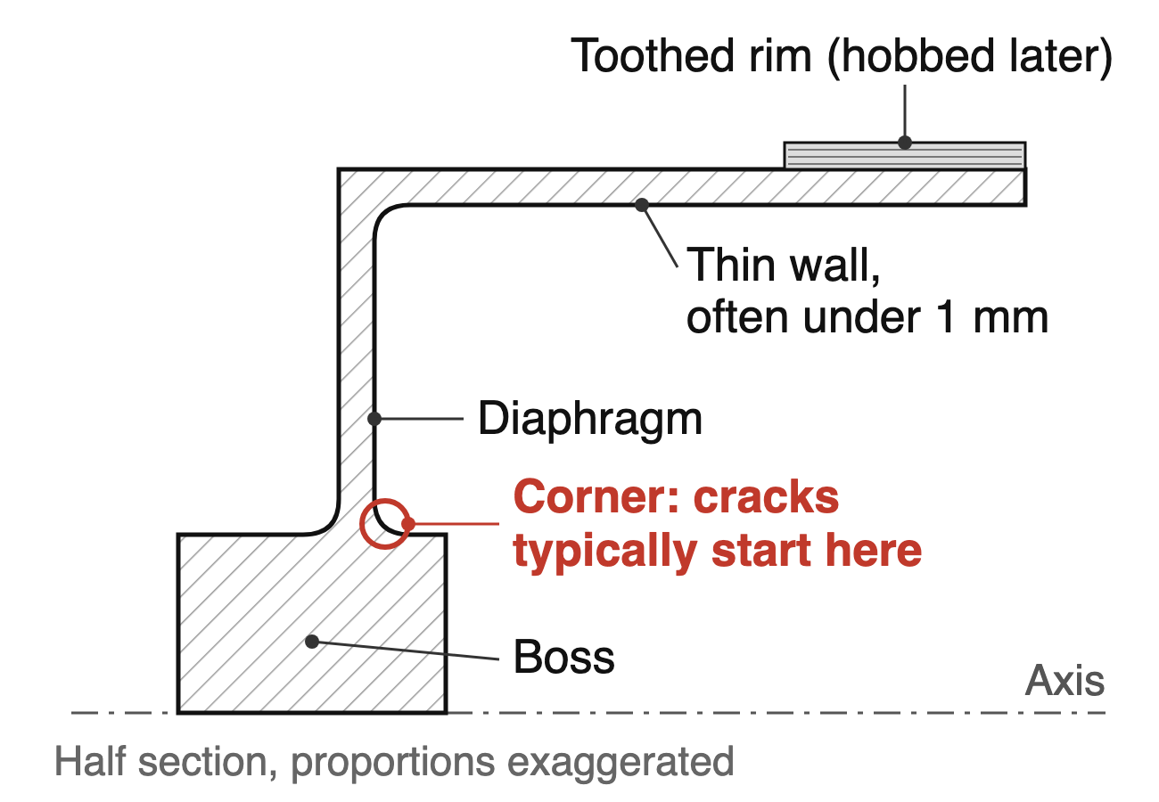
A flexspline has to come off the lathe with a wall that is round and even all the way around, and a diaphragm corner turned to the drawing with no chatter marks or tool-path steps on it. That wall is often less than a millimeter thick.
The reason is how the part works. A flexspline is a steel cup with fine teeth around its rim. Inside the reducer, the wave generator pushes it into an ellipse, and every turn of the input shaft flexes it again.
Where it usually breaks is well documented. Shuting Li of Shimane University describes fatigue breakage at the corner where the diaphragm meets the boss as a typical failure of these gears. An uneven wall bends unevenly, and a mark at that corner sits right where the cracks start.
This article covers the turning work on the cup, before and after heat treatment. The teeth are cut on a gear machine and aren’t part of it.
Where a thin cup goes wrong on a lathe
The chuck shapes the part. A thin ring squeezed by three jaws goes slightly out of round. You turn it perfectly round while it’s held. Then you release it, it springs back, and the high spots from the jaws become low spots in the finished part.
A machinist on the eMastercam forum ran into this with 6-inch aluminum tubing with a 0.75-inch wall in an 8-inch power chuck. Dropping the chuck pressure to its 50 psi minimum didn’t cure it. One reply put it this way: what you chuck on carries through to the machined surface if the part isn’t round.
He got flat parts after clamping a ring in the jaws at minimum pressure and reboring the 6-inch jaw seat and its bottom face, so the jaws matched the part.
Turning the pressure down wasn’t the fix. Making the jaws fit the part was. With a wall under 1 mm, that matters even more.
Small wall variation is a big stiffness change. Bending stiffness of a thin wall goes with the cube of its thickness. If one spot is 5% thinner, 0.95³ ≈ 0.86, so that spot is about 14% less stiff in bending. EMAG, which builds flexspline machining lines, says the wall thickness should be constant over the whole circumference. The cup flexes every revolution, so an uneven wall means an uneven bend.
The material is hard by the time you finish. EMAG lists the route as soft turning, hardening and tempering, hard turning of the functional surfaces, a stabilizing temper, honing of the bore as the reference for gear cutting, then hobbing. A common material is 40CrNiMo (SNCM 439) at 38 to 42 HRC after heat treatment. Whatever you leave for the hard-turning pass has to be taken off at that hardness, on a part that still bends easily.
What the lathe has to bring
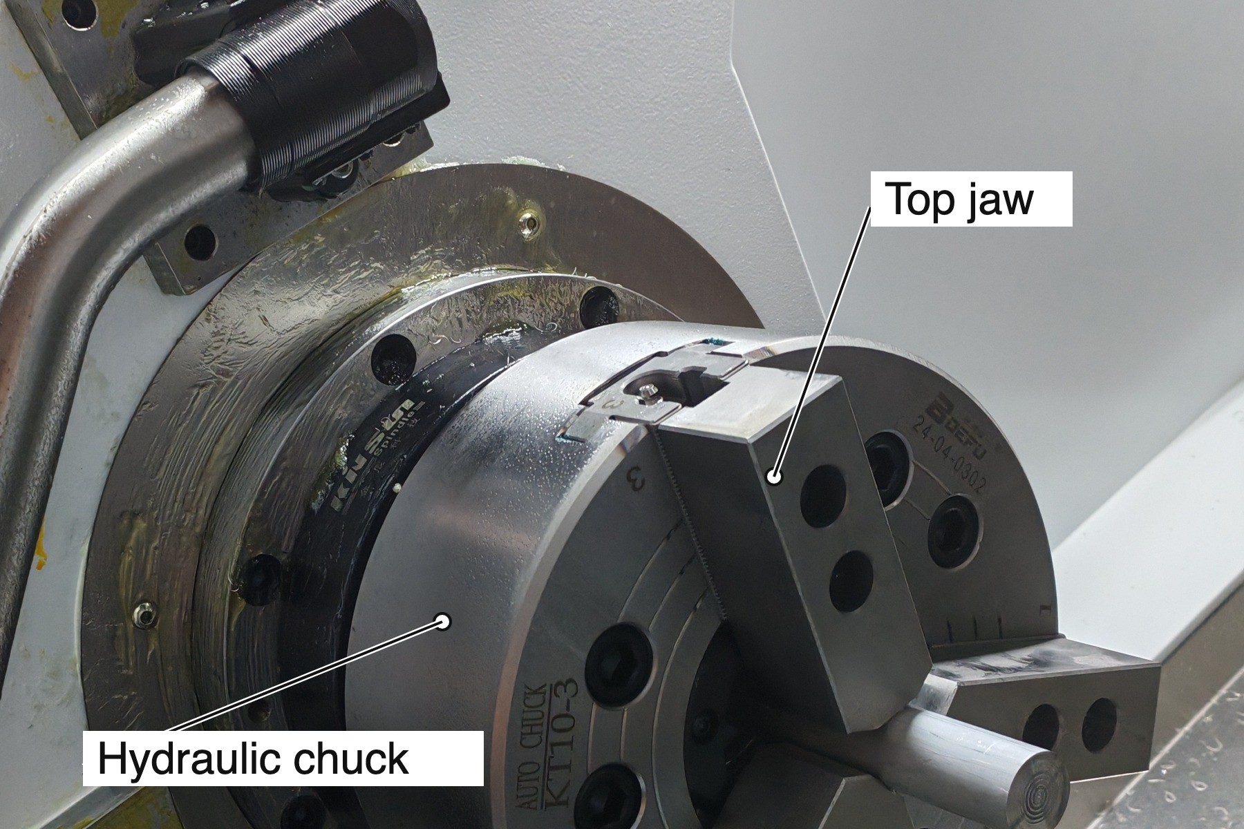
1. Clamping you can turn down and shape to the part. You need chuck pressure that you can set low and repeat, and jaws you can bore to the part so they grip along an arc instead of at a line.
Where the drawing allows, hold the thick boss or a ring that will be cut off later, not the thin wall. EMAG holds flexsplines for gear cutting on hydraulic expanding mandrels, because collets that push in a few places deform the part. The same logic applies at the lathe: for a thin cup, bore the jaws to the part and turn the pressure down.
2. Stiffness for hard turning at the corner. The finishing cuts on the diaphragm corner happen at 38 to 42 HRC, on the spot where Li’s cracks start. Chatter or a step in the tool path there is a mark on the most stressed spot of the part. A rigid bed and turret, and a spindle that runs smoothly at the finishing speed, matter more here than raw power.
3. One axis for the bore and the outside. When the bore and outside are concentric, wall thickness is half the difference between the two diameters, so any offset between them shows up directly as a thick side and a thin side. Turn the outside and the bore in the same clamping where you can, so both share one axis. If you must flip the part, hold it on a surface you just turned, not on a raw one.
Li attributed a slight asymmetry in the measured diaphragm stress signals mainly to assembly misalignment between the flexspline and the circular spline. Keeping the boss and the cup on a common axis helps control that alignment.
4. A plan for two trips to the lathe. Soft turning before heat treatment and hard turning after are two separate setups, with heat-treatment distortion in between. Leave even stock for the hard pass, and decide which turned surfaces will carry the datum to the honing and hobbing steps.
Measure wall thickness off the machine on a fixture that doesn’t squeeze the part. A gauge that clamps hard can show you the distortion it just caused. When you compare lathe offers, ask for a trial cup turned with the proposed jaws and pressure, then measured after release.
What you don’t need to pay for
The teeth are hobbed on a gear machine, and the cup itself is a turned, axisymmetric part, so turning it doesn’t call for a Y axis. Size the swing around your blank and the jaws or fixture, not around the biggest machine on the quote. Live tooling is worth adding only if you want non-turned features, such as holes in the boss, finished in the same setup.
Flexsplines are one part of the reducer. The housing and bearing seats around it have their own problems; our article on robot joint housings covers those.
The bottom line for the machine
- Chuck pressure you can set low and repeat, and soft jaws bored to the part
- Enough stiffness to hard-turn the diaphragm corner without chatter
- A setup that turns the bore and outside on one axis, checked on a released part
How we’d set up a lathe for flexspline cups
For this turning work, we’d start by checking your drawing against the 400T in our slant-bed lathe series: 480 mm maximum disc diameter, a 6-inch or 8-inch chuck, spindle speed up to 5,000 or 3,500 rpm depending on the spindle, and X/Z repeatability of ±0.003 mm.
The hydraulic chuck pressure can be set low for thin walls, and we’d fit soft jaws bored to your part. Our lathes have done hard turning on hardened steel around 40 HRC. Some of our customers build humanoid robots and machine other harmonic reducer parts on our four- and five-axis machining centers.
If you’re planning flexspline production, send us the drawing with material, hardness, wall thickness and the corner radius. We’ll suggest the lathe, the clamping and how to split the turning.
Sources
- Shuting Li, Diaphragm stress analysis and fatigue strength evaluation of the flex-spline, a very thin-walled spur gear used in the strain wave gearing, Mechanism and Machine Theory 104 (2016) 1–16
- EMAG, Flexspline machining for harmonic reducers
- eMastercam forum, calling all power chuck gurus, May 2009
- CHANSIN CNC slant-bed lathe series specifications
- Featured image: Twdragon, Wikimedia Commons, CC BY-SA 3.0, cropped