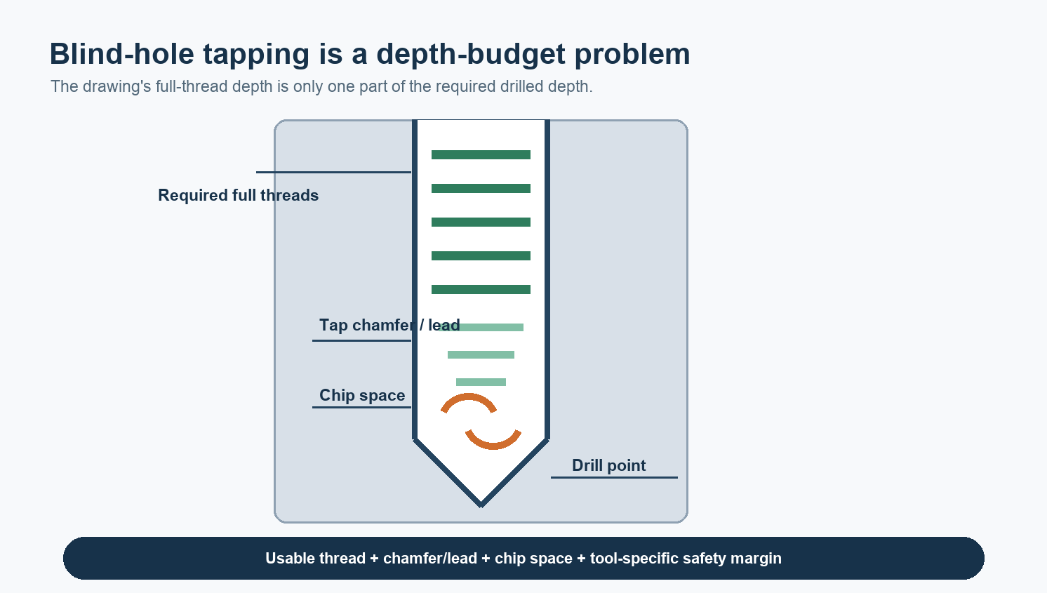
A tap that breaks near the bottom of a blind hole is often running out of process space, not simply suffering from weak tool material. The programmed thread depth may leave too little room for the tap’s chamfer, the drill point, chips and the motion needed to stop and reverse. If the tap geometry also sends chips toward the wrong place, torque can rise sharply just as the tool reaches its deepest position.
The fastest way to diagnose the failure is to start with when it happens. A tool that breaks on entry suggests a different problem from one that reaches depth, begins to reverse and then snaps. Hole depth matters, but it should be checked as part of a complete depth and chip-flow chain.
Start with the point in the cycle where the tap fails
“Near the bottom” can describe three different events. The tap may break while its chamfer is still cutting, at the commanded bottom position, or during reversal. Those events load the tool differently.
| Failure pattern | First mechanisms to examine | What would weaken that diagnosis |
|---|---|---|
| Breaks soon after entry | Undersized or hardened pilot hole, misalignment, excessive runout, wrong feed synchronization | The same tool cuts the first part of every hole cleanly and only fails at full depth |
| Torque rises as depth increases | Chip packing, poor lubrication at depth, unsuitable flute direction, excessive thread engagement | Short, freely evacuated chips and stable torque through the full cut |
| Breaks at the stop or on reversal | Insufficient bottom clearance, unfinished chip roots, chips trapped behind the lands | Generous verified clearance and failure at unrelated depths |
| Fails randomly from hole to hole | Variable pilot-hole size, chip recutting, contamination, tool wear, inconsistent clamping or synchronization | A repeatable torque spike at the same axial position |
Build the blind-hole depth budget
The depth on the drawing usually describes the length of acceptable full thread. A cutting tap cannot produce full thread along its entire chamfer because the first chamfer teeth remove only part of the thread profile. The pre-drilled hole must also accommodate the drill point and enough space below the cutting zone for the process to stop and reverse without compressing chips into the bottom.
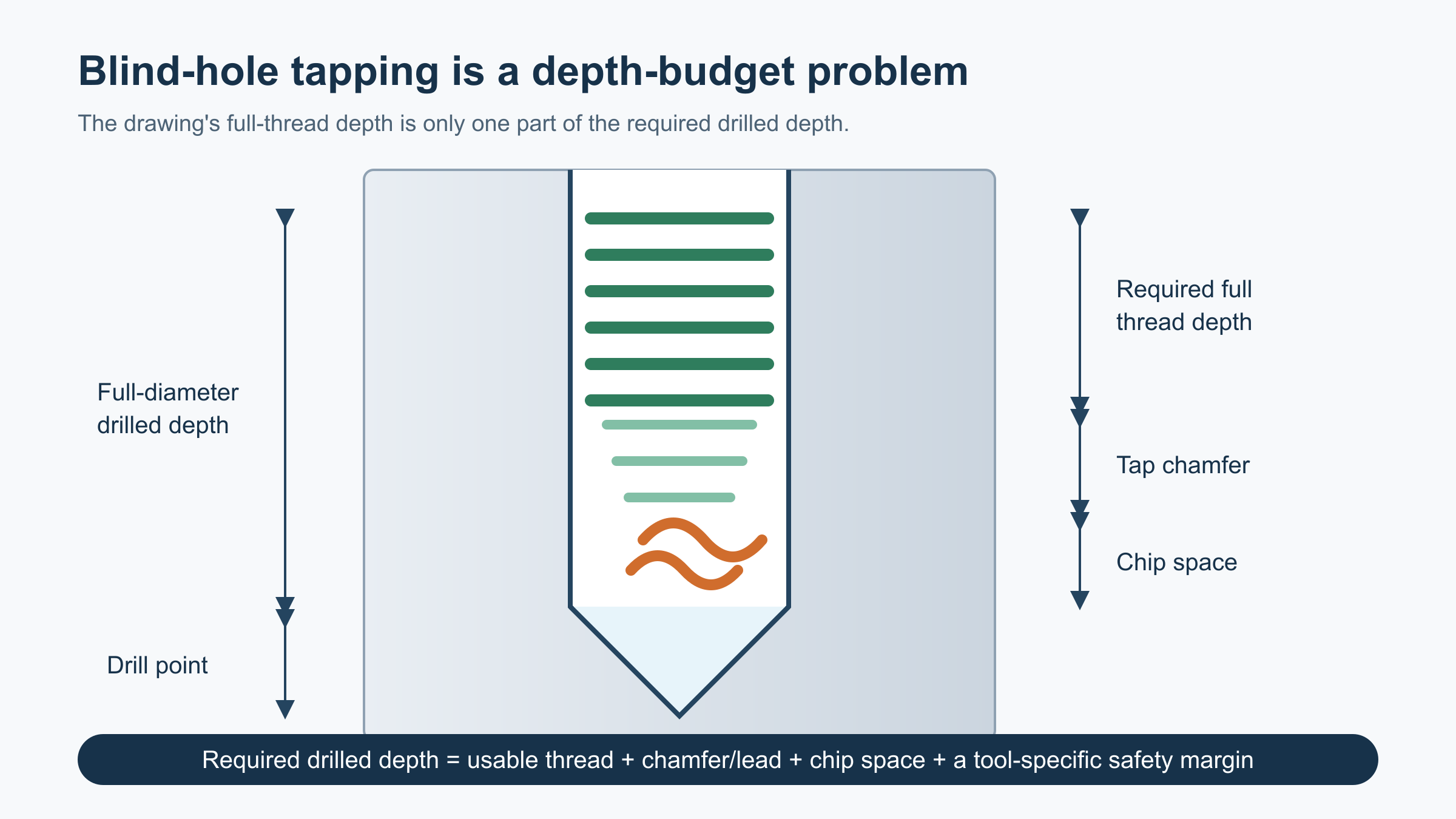
Walter’s threading handbook expresses the relationship as drilling depth greater than or equal to usable thread depth plus chamfer length plus a safety margin. It also distinguishes the full-diameter portion of a drilled hole from the pointed end. That distinction matters: the tap cannot use the conical drill point as if it were full-diameter chip space.
There is no responsible universal answer to “How many extra millimetres should I drill?” A short-chamfer bottoming tap, a long-chamfer tap, a form tap and a spiral-flute tap do not need the same allowance. Thread pitch, chamfer form, drill geometry, material ductility and machine deceleration also change the result. Use the tap manufacturer’s dimensional data and confirm the actual drilled profile rather than adding an inherited shop rule to the print.
Chip direction matters before chip volume does
In a blind hole, the desirable chip path is normally back toward the hole entrance. Right-hand spiral-flute taps are commonly used for long-chipping materials because the helix helps carry chips back toward the shank. Straight-fluted taps do not actively transport chips in the same way; they can work well in short-chipping materials or with suitable internal coolant, but chips can accumulate at the bottom if the process does not remove them.
Spiral-point taps push chips forward in the feed direction. That is useful in a through hole, where the chip has an exit. In a conventional blind hole it can send chips into the space the tap needs at the bottom. Tool families and specialized geometries create exceptions, so the flute style should be checked against the manufacturer’s stated blind-hole application rather than selected by name alone.
Chip form provides direct evidence. Long nests around the tap, packed chips in the flutes, or chips compressed into the pilot-hole bottom support a chip-control diagnosis. Clean, short chips with no buildup shift attention toward hole size, synchronization, runout, lubrication or the tap itself.
Why reversal can be the highest-risk moment
When a cutting tap reaches depth, the chamfer teeth may still be forming chips. As rotation reverses, those partially formed chips contact the backs of the trailing lands and must be sheared off. Walter’s process description shows that reverse torque can rise sharply during this step. A through-hole tap geometry used in a blind hole can make that reversal less forgiving because its chamfer clearance and chip behavior were designed for a different exit condition.
This is why a tap can reach the programmed Z position without an alarm and still break a fraction of a second later. The deepest position is not merely an endpoint; it is a transition from cutting to chip separation and reverse motion.
More hole depth will not fix every tap failure
If the tap breaks before it approaches the bottom, verify the pilot hole first. A worn drill, material springback, built-up edge or an incorrect drill size can raise thread engagement and torque throughout the cut. Check the hole after drilling rather than assuming the programmed drill is producing its nominal diameter.
Next, examine the assembled tool path. Runout and angular error can make one land carry more load, especially on small taps. Clean mating surfaces, correct collet range and restrained stickout matter here; the same assembled-system logic used when diagnosing toolholder runout on small end mills also applies to a tap, even though the cutting process is different.
Rigid tapping also depends on spindle-axis synchronization. Pitch error accumulates quickly if spindle rotation and axial feed do not remain coordinated. A tension-compression holder may absorb limited mismatch in a process designed for it, but it should not be used to hide an incorrect feed, wrong pitch or machine fault. Lubrication, coating, work hardening and tap wear can further raise torque without any change to the programmed depth.
A practical diagnostic sequence
- Record the failure phase. Note whether the tap breaks on entry, during steady cutting, at the bottom or on reversal.
- Section or measure a representative pilot hole. Confirm full-diameter depth, drill-point depth, diameter, taper and bottom condition.
- Compare the depth chain with the tap drawing. Include required full thread, chamfer/lead, chip space and the manufacturer’s safety allowance.
- Inspect chip evidence. Check flute loading, chip direction and material at the hole bottom.
- Verify the tool application. Confirm that the exact tap geometry is intended for the material and blind-hole condition.
- Check synchronization and assembled alignment. Check pitch/feed commands, holder condition, runout and unnecessary stickout.
- Change one variable and run enough holes to see a pattern. Compare peak torque or spindle-load behavior, chip form, thread quality and tool condition rather than judging one successful hole.
Engineering conclusion
A blind-hole tap that breaks near the bottom is often signaling that the process has no room left for its chamfer, chips and reversal. Build the depth budget from the actual tool data, then check whether the selected geometry moves chips toward a real exit. If the failure occurs earlier or randomly, return to pilot-hole size, alignment, synchronization, lubrication and wear instead of drilling deeper by default.
Frequently asked questions
Should a blind-hole tap touch the bottom?
No. Contact with the bottom is not a depth-control method. The process needs verified clearance for the tap geometry, chips and reversal, based on the actual tool manufacturer’s data.
Is a spiral-flute tap always best for a blind hole?
No. It is a common choice for long-chipping materials because it pulls chips toward the entrance, but short-chipping materials, internal coolant, thread depth and specific tool designs can justify another geometry.
Will peck tapping solve chip packing?
It may help in some tool-specific processes, but repeated reversals can also add cycle time and edge loading. Use a peck cycle only when the tap manufacturer and machine process support it; first confirm that tool geometry, lubrication and available chip space are correct.
Sources and Method
- Walter, Product Handbook: Threading with Walter Prototyp — blind-hole depth calculation, tap types, chip transport, chamfer behavior and reversal torque.
- FANAR, “How to Choose the Right Tap? Guide to Chip Flutes and Chip Evacuation” — supplementary explanation of tap geometry and chip direction.
- Protool, “Tap Breakage Causes and How to Prevent Them” — supplementary fault-pattern coverage used to organize the diagnostic sequence.
The article combines manufacturer technical guidance with a process-stage diagnostic method. It intentionally gives no universal depth allowance or tapping parameter because those values depend on the exact thread, tool, material and machine process.