The caliper says the hole is on size. The roundness report says it’s scrap. Both can be right, and the argument between them is where the diagnosis starts.
When a circularly milled hole fails on form, the cause is usually one of four things: the measurement, the cutting system, the clamping, or the machine’s circular motion. Change one thing at a time, keep the conditions written next to each result, and the list gets short quickly. Change the compensation first, and you may hide the real problem in one hole while creating a new one somewhere else in the work envelope.
Diameter, roundness and position are three different questions
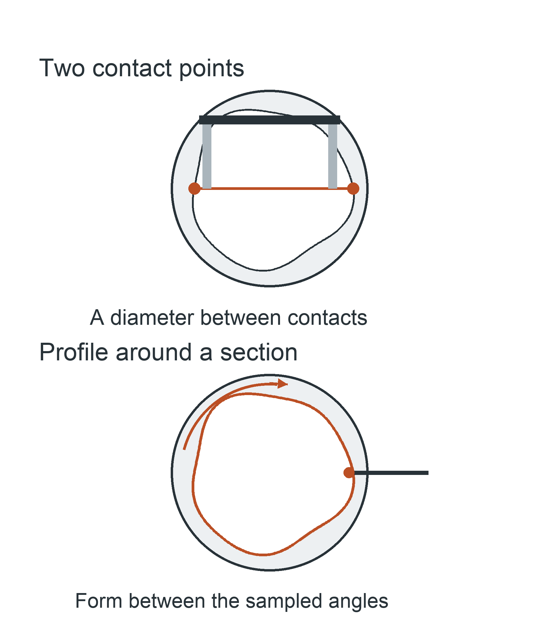
A caliper or a two-point bore gauge measures the distance between two opposite points. A roundness check follows the whole profile around one section. That difference matters more than it sounds.
Writing about turned bar stock, the Precision Machined Products Association warns that a lobed, pseudo-round part can mike as if it were round between two parallel faces, and recommends a three-point gauge where roundness is critical. A hole can hide the same kind of shape, so a single size reading can’t stand in for the profile.
So before anyone touches the machine, ask inspection to confirm the drawing requirement, the measurement plane and the method. Repeat the check at the same depth, and mark where each error sits relative to the X and Y axes. If the fixture might be squeezing the part, measure it clamped and released.
Choose the next comparison
| What you see | Check next | What it narrows |
|---|---|---|
| Size off, shape fine | Tool size and offset | Diameter control |
| Flats that repeat | Angle and direction | Circular motion |
| Shape changes with load | Stickout and clamping | Cutting effects |
Position is its own question: a perfectly round hole can still be in the wrong place. If you’re deciding whether another operation should fix size, straightness or location, read our reaming versus boring comparison. Here we’re tracing the shape that circular milling leaves behind.
Check the cutting system before the compensation table
Write down the cutter, the holder, the actual stickout and the finishing allowance. Then look for uneven stock left by roughing, a worn edge, or chips being cut a second time. Any of these changes the load as the tool goes around the hole, even though the programmed circle never changes.
Next, try a shorter, better-supported tool where the part allows it, with everything else the same. Sandvik Coromant’s hole-milling guidance treats long overhang as a limit when milling holes. The reason is basic mechanics: for the same tool section and the same side load, a longer tool bends more. If the hole gets rounder with less overhang, put the cutting system at the top of your list. For more on reach and vibration, see our tool-stickout milling guide.
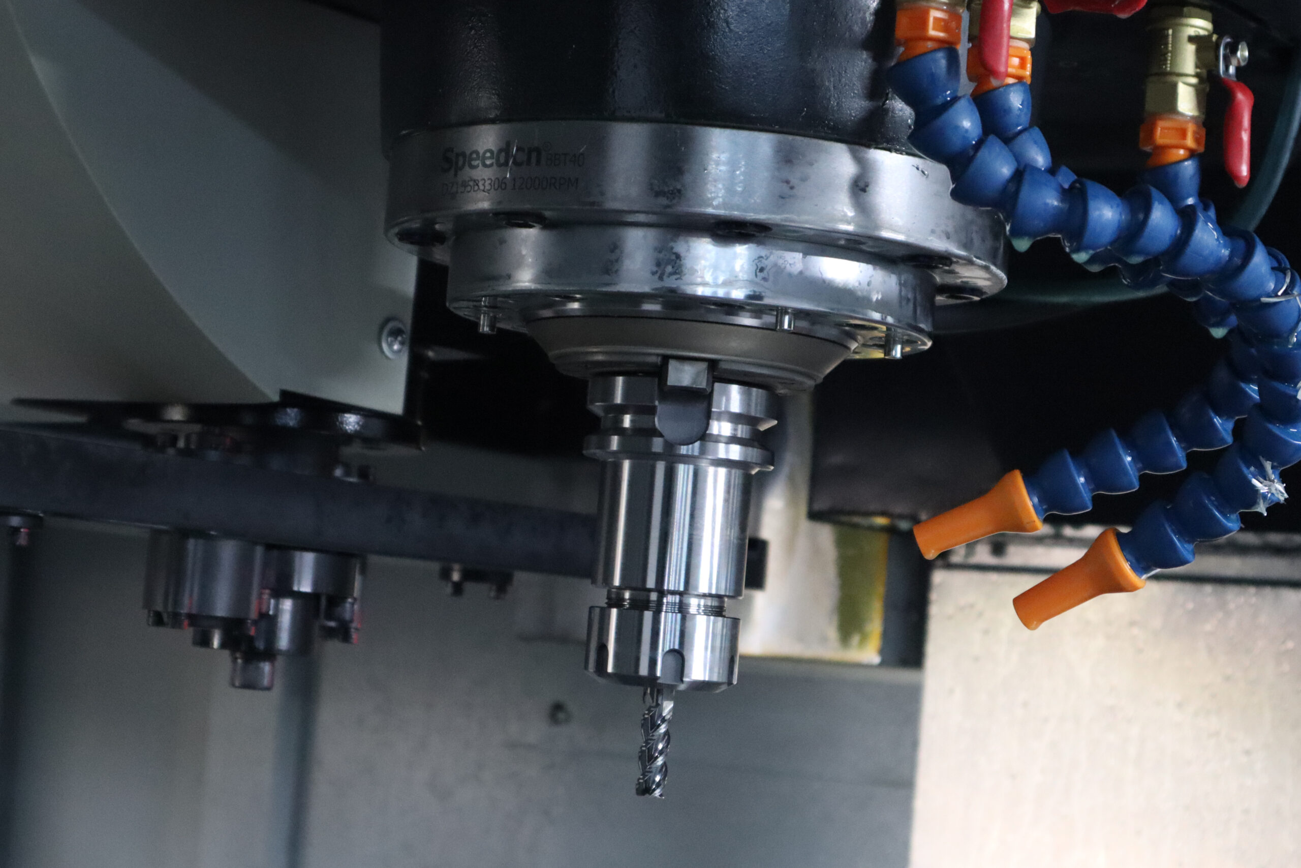
A lighter finishing pass tells you the same thing from another angle. If the profile improves when the load drops, look at tool bending, uneven stock and workholding. Keep both traces, the original and the comparison, rather than a single diameter number.
This is a direction for investigation, not a verdict. Cutting errors and axis errors can show up together, and changing the load can change how each one looks. If a repeatable pattern is still there once the cutting side is sorted, it’s time to look at the machine’s motion.
Map the pattern onto the machine axes
In XY circular interpolation, each axis reverses direction at two points on the circle: X at the 3 and 9 o’clock positions, Y at 12 and 6. If the same short flat or spike keeps coming back at those points over repeated cuts, the axes are a suspect. Note the feed direction and where in the work envelope you cut, and change one of those at a time.
Don’t jump from there to a worn ballscrew. Haas’s ballbar interpretation guide separates backlash, reversal spikes, squareness, servo mismatch and errors introduced by the test hardware itself, and several of them look alike at a glance. The shape of one hole points you to the right test. It can’t name the part that’s worn.
Record feed, circle size, position and the machine’s thermal state with every comparison. Thermal growth can change the result, so compare traces taken at a documented, comparable thermal state. If the pattern moves with temperature or position, that belongs in the service report too.
Take the cut out of the picture: a ballbar test
A ballbar measures how the distance between a fixed table mount and the spindle changes as the machine runs a circle. It takes the cutting load and the workpiece out of the picture, which makes it a good way to look at axis motion.
Check the test setup and its repeatability first, because the bar, its ball seats and how they’re mounted can add errors of their own. Your service team can run it clockwise and counterclockwise and compare the two.
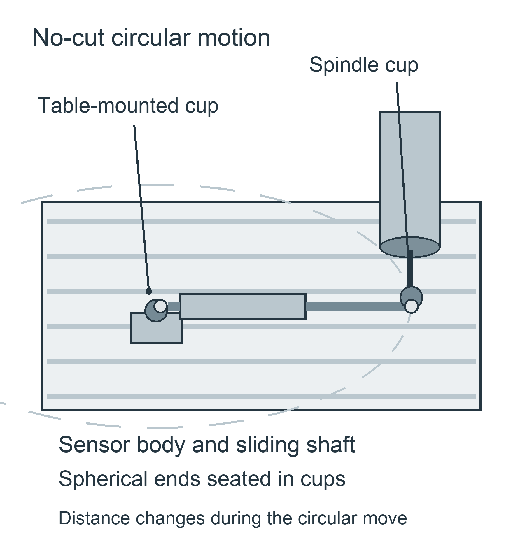
The test radius changes what you’ll see. Renishaw notes that large circles are better at showing geometry errors, while small ones are more sensitive to servo mismatch and lag. So match the radius and feed to the question you’re asking, and keep them with the trace.
Put the two results side by side. A repeatable no-cut anomaly near the axis reversals makes a strong case for looking at the machine’s motion system. A clean no-cut trace next to a load-sensitive machined hole sends you back to the cutting side.
What to send before anyone adjusts the machine
Give your service team the drawing requirement, the measurement method and the traces, the cutter and holder details, the stickout, the clamping layout and the cutting conditions. Add the angular error map and any no-cut reports with their radius, feed, direction and position. With that, they can reproduce the condition instead of guessing from a photo.
Leave servo tuning and compensation to whoever is responsible for the machine, working from its own documentation. An adjustment made to fix one hole’s shape can move the error somewhere else in the work envelope.
Choose the structure and checks around the cut
Our V series runs linear guideways on all three axes and suits lighter cutting, including aluminum work. The L series pairs linear X and Y guideways with a box-way Z axis for heavier cutting. The material, the tool reach and the load the job really needs should decide between them.
For work like this we’d fit workpiece probing and tool measurement where they help you catch setup and tool problems early. They help you confirm the workpiece datum and the measured tool length or diameter earlier in the process.
If you’re discussing a hole problem like this with us, bring the measurement traces and the machining conditions together. That’s what lets us talk about machine structure and the checks your job actually needs.
Sources and Method
- Haas: Renishaw Ballbar Test, Plot Interpretation, Mills (updated 23 June 2020), error patterns and test-hardware effects
- Renishaw: Ballbar testing explained, circular-motion measurement, test directions and radius sensitivity
- Sandvik Coromant: Milling holes and cavities/pockets, hole-milling methods and long-overhang limits
- PMPA: 5 Things To Know About Triangle Effect, Pseudo-Roundness, and Lobing, why two-point gauges miss lobed parts
Chansin CNC organized this diagnostic order from the sources above.