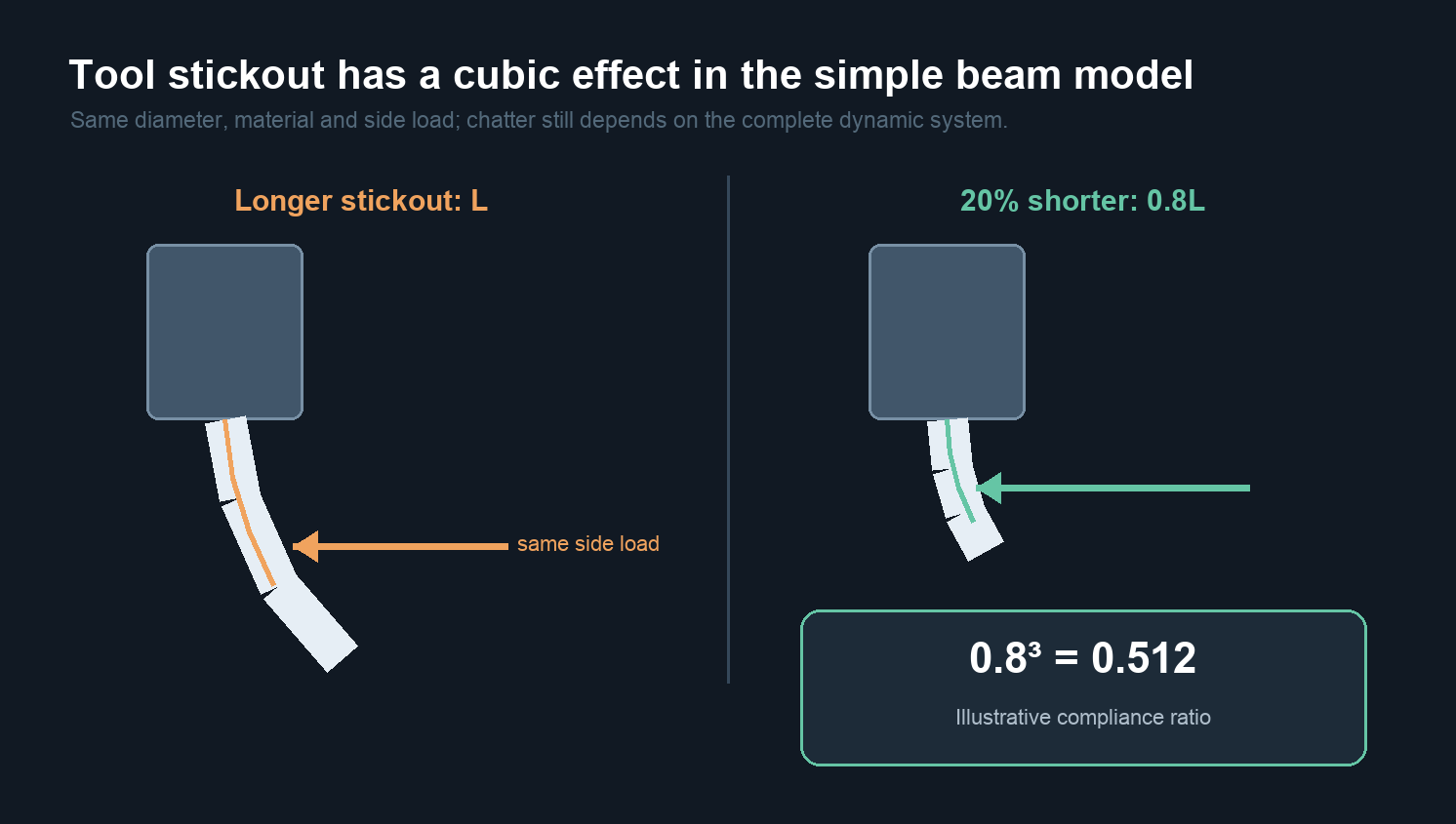
A small increase in tool stickout can turn a quiet milling cut into chatter because length strongly affects bending compliance. In the simplest cantilever model, deflection under the same side load grows with the cube of unsupported length. That makes shortening the tool one of the first changes to try when the geometry allows it.
The model is useful for understanding sensitivity, but it does not predict chatter by itself. Chatter is a dynamic interaction among the spindle, holder, tool, workpiece, engagement and cutting speed. Stickout changes that system; it is not the only variable in it.
Define the length before changing it
Tool stickout is the distance from the holder’s effective support point to the relevant cutting zone. It is not automatically the overall tool length, flute length or neck length. A long-flute end mill may have more cutting length than the operation needs, while a long-reach tool may use a reduced neck to clear a wall. Both can be less stiff than a short standard tool of the same cutting diameter, but for different geometric reasons.
Measure and record the assembled stickout, not the value assumed in CAM. Two sister tools programmed identically can behave differently if one is clamped farther out. Also confirm the minimum insertion and clamping requirements of the tool and holder; shortening stickout must not mean clamping on flutes, a transition or an unsuitable part of the shank.
Why the length effect becomes large so quickly
For a uniform cantilever beam with a side load at its end, the simplified elastic deflection is:
δ = F L3 / (3 E I)
Here, F is the side load, L is unsupported length, E is elastic modulus and I is the section’s second moment of area. The expression assumes a simple beam, small elastic deflection, a fixed support and constant cross-section. A real milling assembly violates several of those assumptions, but the length sensitivity remains a powerful diagnostic clue.

In that example, the shorter assembly has about 51% of the calculated static compliance of the original. The example does not say surface error will fall by 49%, because cutting force may change and the tool-holder-spindle system has joints, damping and multiple vibration modes. It says a modest geometric change can be large enough to deserve attention before parameters are tuned around an unnecessarily flexible setup.
Static deflection and chatter are related but different
Static deflection moves the tool while force is applied. Regenerative chatter occurs when vibration left by one tooth changes the chip thickness seen by the next tooth, feeding energy back into the cut. Natural frequencies, damping, tooth-passing frequency and radial immersion determine whether that feedback grows or decays.
Shortening stickout usually increases stiffness and shifts the assembly’s dynamic behavior, which can widen the stable region. It does not guarantee that the current spindle speed will become stable. A speed change, lower radial engagement, different pitch, fewer teeth, a stiffer workholding setup or a damped tool may still be necessary.
| Change | Main effect | Important limitation |
|---|---|---|
| Shorten unnecessary stickout | Reduces the most direct geometric lever on tool bending | Requires clearance and correct shank engagement |
| Reduce radial engagement | Can reduce force and change directional excitation | May increase cycle time or alter chip thinning |
| Change spindle speed | Changes tooth-passing frequency and regenerative phase | A small arbitrary reduction can move into a less stable region |
| Use a damped or larger-diameter system | Adds damping or section stiffness for necessary reach | Tool access, holder size, cost and operating range still matter |
Change the setup in an order that preserves evidence
First, confirm that the sound and surface pattern are actually chatter. Periodic marks can also come from runout, a chipped edge, spindle error, workholding movement or interrupted engagement. Check whether the vibration frequency and mark spacing track spindle speed, tooth count or a structural feature.
Next, shorten only the unnecessary extension while keeping the same tool, holder, program, material and workholding. Test the current and shorter setups under the same conditions. Compare sound, surface pattern, spindle load, edge condition and dimensional result over enough cutting distance to see whether the change repeats.
If the problem improves but does not disappear, adjust one dynamic variable at a time. Spindle speed is often more informative than a blanket feed reduction because it changes the excitation frequency. Radial engagement and toolpath can reduce force and change its direction. Maintain chip thickness within the tool maker’s range; reducing feed per tooth until the edge rubs can add heat and instability rather than solve them.
Runout can imitate a stickout problem
Longer extension can amplify the displacement caused by angular error in the spindle-holder-tool stack. One flute may then carry more of the cut, producing once-per-revolution force variation and uneven wear. Measure the assembled tool near the cutting position and check repeatability after reclamping. The detailed method is covered in this guide to toolholder runout with small-diameter end mills.
If static runout improves but chatter remains, that is useful evidence. Return to the dynamic system instead of chasing an ever-smaller indicator value.
When short stickout is not enough
Deep cavities, tall walls and fixture interference can impose a minimum reach. In those cases, tool diameter, neck diameter, holder interface and cutting-force direction become more important. Sandvik Coromant’s long-overhang guidance emphasizes controlling force direction and using vibration-damped tooling where the reach demands it.
The workpiece may also be the flexible element. Thin walls can vibrate even with a short, rigid tool. Changing the machining sequence, leaving temporary support stock, improving fixture contact or reducing local radial engagement may then produce a larger benefit than another stickout change.
Engineering conclusion
Use the cubic length relationship to recognize why unnecessary stickout is expensive in stiffness. Shorten the assembled tool to the minimum safe reach, test the change under the same cutting conditions, and then tune speed, engagement and toolpath with a clearer baseline. Treat the calculation as a sensitivity model, not a chatter prediction: the stable process belongs to the complete machine-holder-tool-workpiece system.
Frequently asked questions
Does 20% less stickout always cut deflection in half?
Only in the stated simple-beam comparison with the same load, material and section. Real cutting force and joint behavior can change, so use 0.512 as an illustration of sensitivity, not a guaranteed shop result.
Should feed or spindle speed be reduced first?
Remove unnecessary stickout first when possible. For remaining chatter, a deliberate spindle-speed change can be more informative than a blanket feed reduction. Keep chip thickness within the tool manufacturer’s range.
Can a longer flute solve reach without affecting stiffness?
No. A longer flute or reduced neck changes the weakest section of the tool. Choose only the cutting length and reach the feature needs, while maintaining clearance and proper clamping.
Sources and Method
- MIT 3.052 Course Reader, Appendix Lecture 2 — derivation of the elastic tip deflection of a simple cantilever under an end load, including δ = FL³/(3EI).
- Seco Tools, “Reduce tool deflection with a short reach” — manufacturer guidance on overhang and tool deflection.
- Sandvik Coromant, “Tips film: Long overhang” — force direction and vibration-damped tooling for long-reach operations.
- Machining Doctor, “Endmills Deflection” — supplementary explanation of stickout, tool geometry and simplified beam deflection.
- MSC, “Fix Milling Chatter” — supplementary coverage of chatter variables and troubleshooting.
The calculation uses the standard Euler–Bernoulli cantilever relation only as a normalized comparison. It does not estimate cutting force, damping, natural frequency or a stability lobe.