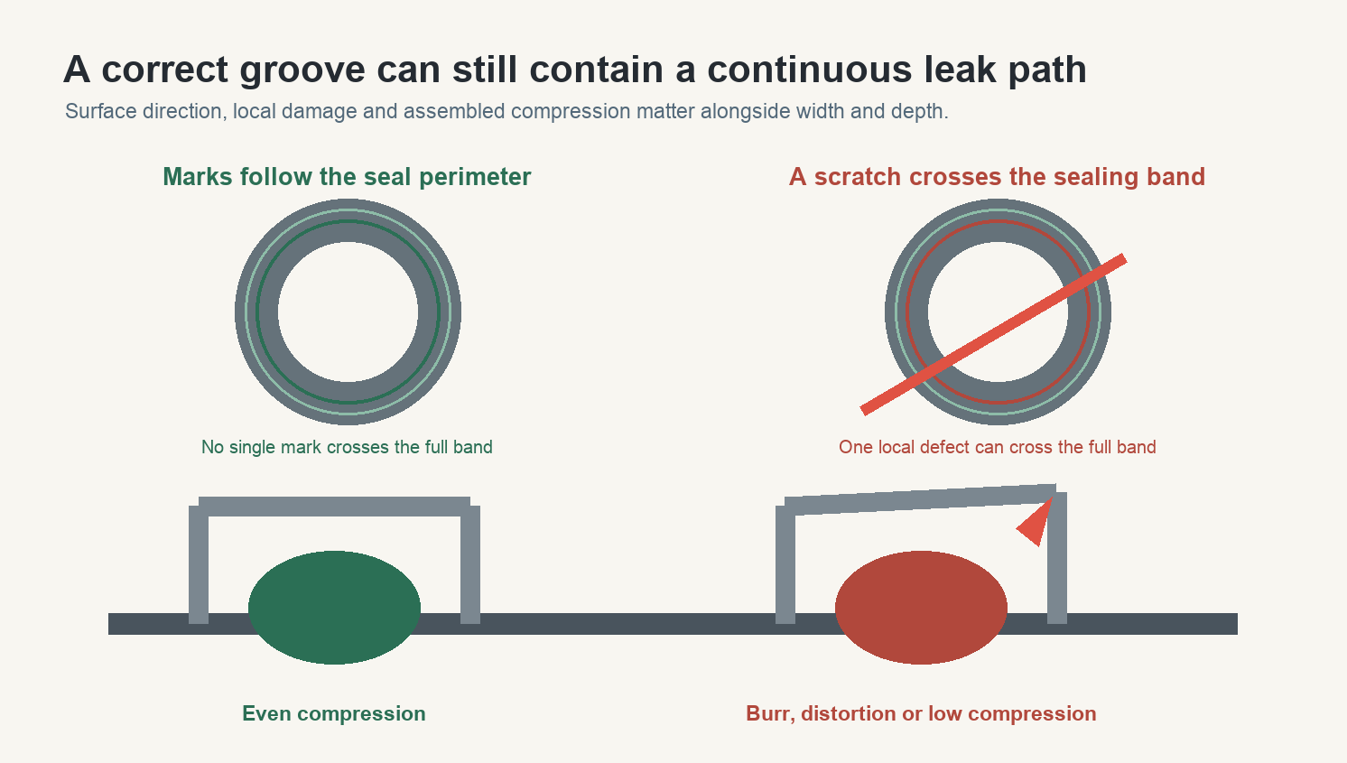
An O-ring groove can pass width, depth and diameter inspection and still leak because those dimensions do not describe the complete sealing interface. A scratch that crosses the sealing band, a burr that damages the O-ring during assembly, a warped mating face or insufficient assembled compression can create a continuous path around an otherwise correct groove.
Surface finish should therefore be judged by more than one average roughness value. Direction, isolated defects and the relationship among the groove bottom, sidewalls and mating face all matter. A lower Ra can help, but polishing alone cannot repair the wrong compression or a distorted joint.
A face seal depends on more than the groove bottom
In a static face seal, the O-ring is compressed between the groove and the mating face. The groove controls where the elastomer sits and how much space is available as it deforms. The mating face closes the joint. Sidewalls guide the ring and can affect damage or extrusion under pressure. The seal succeeds only when those surfaces and the assembled joint work together.
A drawing may specify groove width and depth correctly while leaving surface lay, edge condition, flatness or inspection method ambiguous. The manufactured dimensions can then be “in tolerance” while a feature that was never adequately specified creates the leak.
Why the direction of machining marks matters
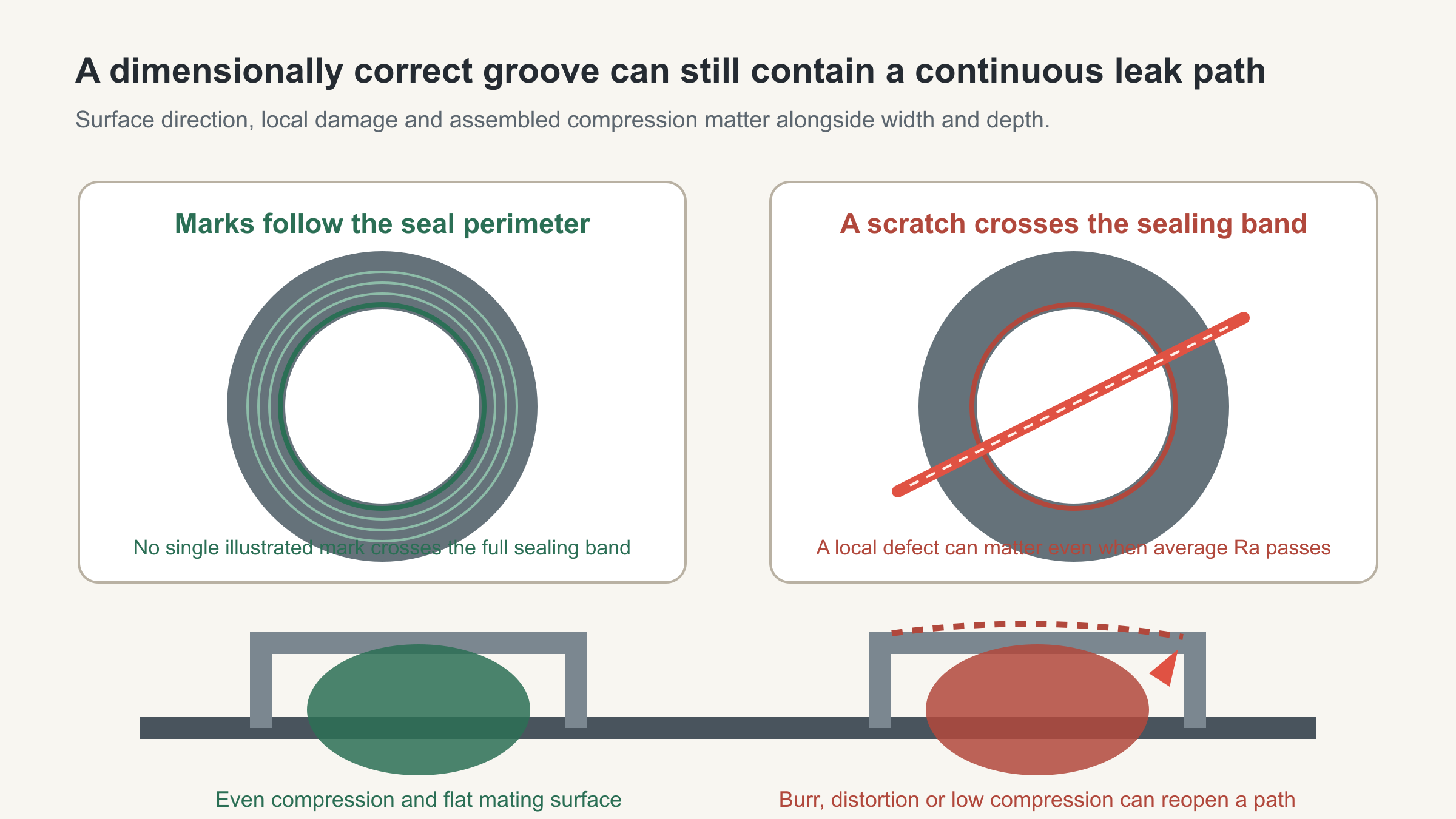
Machining marks that follow the seal perimeter do not automatically make a joint leak-free, but they are less likely to form one continuous route from the pressure side to the atmosphere. A straight scratch or tool mark crossing the entire sealing band can connect those two sides.
Greene Tweed’s leakage study distinguishes circular machining that follows a gland perimeter from straight machining that crosses it. Under the study’s test conditions, machining pattern could have more influence on leakage than the nominal surface-finish value. Technetics likewise illustrates radial marks as an unfavorable flange finish and concentric marks as favorable for a circular seal. These sources do not create a universal finish specification for every elastomer and liquid. They support the mechanism: surface direction can either interrupt or preserve a leakage path.
Why Ra alone can miss the defect
Ra averages vertical deviations along the measured trace. A mostly smooth surface with one deep scratch can still produce an acceptable average, depending on trace location and sampling. If the stylus path does not cross the scratch, the measurement may miss it completely. Rz or a profile trace can reveal different information, but no single parameter replaces a drawing requirement that addresses lay and local damage.
| Inspection result | What it confirms | What it may not confirm |
|---|---|---|
| Groove width and depth pass | Measured geometry at the sampled locations | Actual squeeze after tolerance stack, flatness and assembly |
| Ra passes | Average profile roughness along the measured trace | Lay direction, isolated scratches, pits or burrs outside the trace |
| Visual inspection passes | No visible defect under the chosen lighting and magnification | Subtle topography, embedded debris or the assembled pressure path |
| Leak test passes | Joint performance under the stated medium, pressure, temperature and duration | Different service conditions or long-term permeation and degradation |
Burrs create damage during assembly
A sharp groove edge or small burr can cut, shave or twist the O-ring as it is installed. The groove may look acceptable after assembly because the damaged area is hidden. Deburring must therefore remove loose and sharp material without rolling a large edge into the sealing surface or changing the groove geometry beyond its tolerance.
Cleanliness is part of the same mechanism. A metal chip, fiber or cured residue trapped under the ring can hold the elastomer away from the surface and form a local channel. Clean the groove and mating face, then inspect the seal itself for nicks, flattening, twist and material compatibility before assembly.
Better surface finish cannot fix the wrong squeeze
The O-ring must deform enough to maintain contact, but not be overfilled or damaged. Actual compression depends on groove depth, O-ring cross-section, tolerances, mating-face position and joint deflection. Parker’s O-Ring Handbook treats gland design, material, squeeze, stretch, clearance and service condition as a connected system. The correct values vary with seal type and application.
A warped cold-plate cover or manifold face can reduce compression in one area even when the groove was machined correctly. Bolt spacing and tightening sequence can also bend the joint. This is why leak investigations should connect groove inspection with datum and flatness control. The same system view is useful when evaluating cold-plate joining distortion, datum transfer and leak testing.
Material compatibility and temperature add further limits. Swell, shrinkage, compression set and thermal expansion change contact over time. A finish improvement may delay leakage without addressing the actual material or joint-design problem.
A practical inspection sequence
- Confirm the application specification. Identify the O-ring material, cross-section, groove standard, medium, pressure, temperature and allowable leakage.
- Measure groove geometry in a defined datum system. Check width, depth, diameter or path, corner radii and flatness where required.
- Inspect the sealing band directionally. Look for marks that cross from the pressure side to the outside, not only for a general polished appearance.
- Measure the specified texture parameters. Use the required cutoff, trace direction and sampling locations; do not compare values measured by incompatible methods.
- Check edges, cleanliness and the O-ring. Remove damaging burrs and verify that the ring was not nicked or twisted during installation.
- Evaluate assembled compression and joint distortion. Include tolerance stack, flatness, fastener loading and service deformation.
- Run the specified leak test. Record medium, pressure, temperature, stabilization time and test duration so a pass or failure has a defined meaning.
Separate a true leak from permeation
A rapid pressure loss through an interfacial channel is different from gas permeating slowly through the seal material. Greene Tweed’s paper treats those mechanisms separately and notes that they occur on different time scales. For liquid-cooling hardware, trapped air, temperature change and test-system volume can also affect pressure-decay results. A leak test needs a defined method before it can isolate the groove as the cause.
Engineering conclusion
When an in-tolerance O-ring groove leaks, do not respond by polishing the bottom surface alone. Trace the complete sealing path: groove geometry, surface lay, local scratches, burrs, cleanliness, O-ring condition, assembled compression, mating-face flatness and test method. Dimensions and Ra remain useful controls, but neither one proves that the assembled joint has no continuous leak path.
Frequently asked questions
Is a lower Ra always better for an O-ring groove?
No. The required finish is application-specific, and surface direction or a single deep scratch can matter more than a small change in average Ra. Excessive polishing can also alter geometry or create an unsuitable lay.
Should machining marks be radial or concentric on a face seal?
Marks that follow the seal perimeter are generally less likely to form a direct cross-seal channel than radial marks. The drawing should specify the required lay and finish for the actual seal design.
Can a pressure-decay failure prove the groove is defective?
Not by itself. The fixture, connections, trapped volume, temperature, mating face, O-ring and test method can all affect the result. Localize the leak and correlate it with physical inspection before assigning the cause.
Sources and Method
- Greene Tweed, Methods of Evaluation of Seal Leakage & Prediction of Thermal Degradation — experimental discussion of groove machining pattern, surface finish, true leakage and permeation.
- Technetics, How Does a Seal Work? — surface lay, groove, compression, flatness and flange considerations.
- Parker, O-Ring Handbook (ORD 5700) — gland design, squeeze, material and service-condition framework.
- O-Ring Supply Co., “O-Ring Groove Surface Finish Requirements” — supplementary explanation of Ra, Rz and local surface defects.
No universal roughness, squeeze or leakage value is proposed here. Those limits must be selected from the seal design standard and supplier data for the actual medium, pressure, temperature and joint.