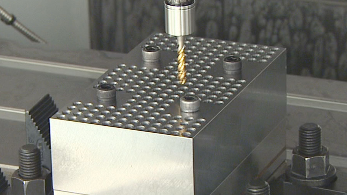
Take a stainless steel valve body that has already spent three hours on the machine, with four M12 blind holes left to thread. A tap would finish each hole in seconds. Break one, though, and you're fishing it out of a part that was nearly done. Whether those seconds are worth that risk is the real question behind tapping versus thread milling, and the machine has to be able to run whichever answer you choose.
Keep tapping when the spindle and Z axis stay synchronized through reversal, the spindle has enough torque at tapping speed, and chips can get out of the hole. Move to thread milling when you need to adjust thread size or can't afford a trapped tap, and your control and CAM can produce the helical path. A capable three-axis VMC does both, so you decide hole by hole, not machine by machine.
| Requirement | Tapping | Thread milling |
|---|---|---|
| Motion | Z feed follows spindle rotation at the thread pitch | X, Y and Z follow a helical path |
| Thread size | Set by the tap | Adjusted through the tool path |
| What to check on the machine | Synchronization and torque at tapping speed | Helical interpolation and how the axes hold the path |
Synchronization and interpolation ask different things of the control
In rigid tapping, Z has to advance exactly one pitch per spindle revolution, on the way in and through the reversal on the way out. Any mismatch turns into axial load on the tap. That's why holders such as OSG's SynchroMaster add a micro compensator to reduce axial force. Such a holder soaks up small errors, but it won't make up for a machine that can't hold synchronization.
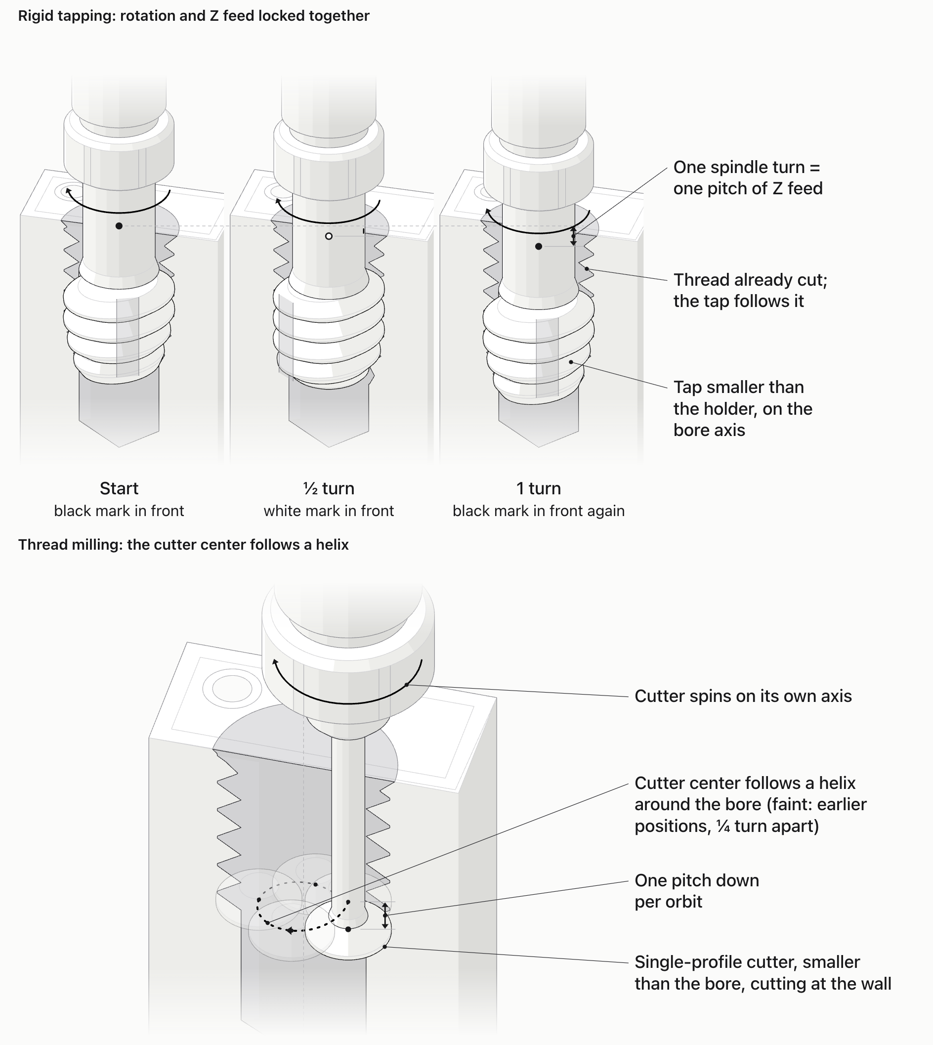
Thread milling asks for something else. The cutter circles the bore, and Z drops one pitch for every circle, so X, Y and Z have to move together. Before you plan a job this way, check that your control does simultaneous three-axis helical interpolation and that your CAM post writes it out correctly.
Maximum rpm won't tell you the tapping limit
Maximum rpm and rated power don't tell you how much torque the spindle has at low speed, and a large thread in stainless is tapped slowly. What you need to know is the torque at your planned tapping speed, read from the spindle's torque curve, and on a geared spindle, in the gear you'll use.
If you're asking a machine builder whether a VMC can tap M12 in stainless, give them the material, thread size, depth and holder, and ask them to check it against the spindle's torque curve.
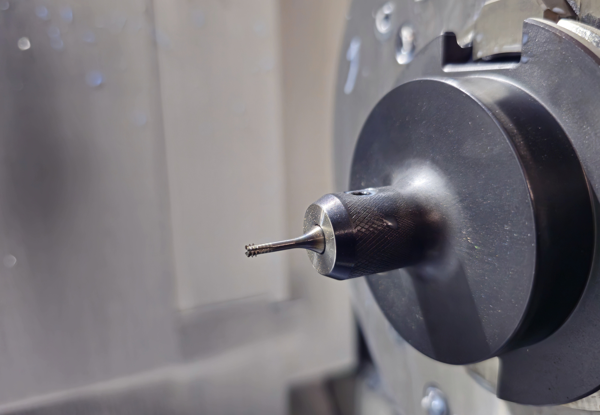
Thread milling loads the machine in a different way: a small cutter swings round a tight circle under cutting force, and the axes have to stay on that path. Sandvik's thread-milling guidance ties its cutting data to this helical movement. Watching the cutter spin in the air at programmed speed won't tell you how the axes cope under load, so judge it in a test cut.
Count the hole-bottom space and the cost of breakage
A blind hole needs room below the last full thread for the tap's chamfer, for chips and for the reversal. Compare the full-thread depth on the drawing with the drilled depth you can actually have. If taps are already breaking near the bottom, our blind-hole tap breakage guide works through that fault.
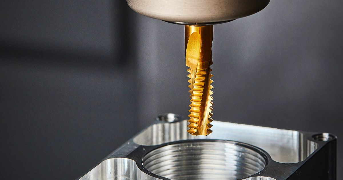
Breakage changes the sums. A thread mill is smaller than the hole, so if one breaks it's often easier to get out than a tap jammed in the thread, a point EMUGE makes. On a valve body like the one above, that can matter more than a few extra seconds per hole.
Check what the feed value describes
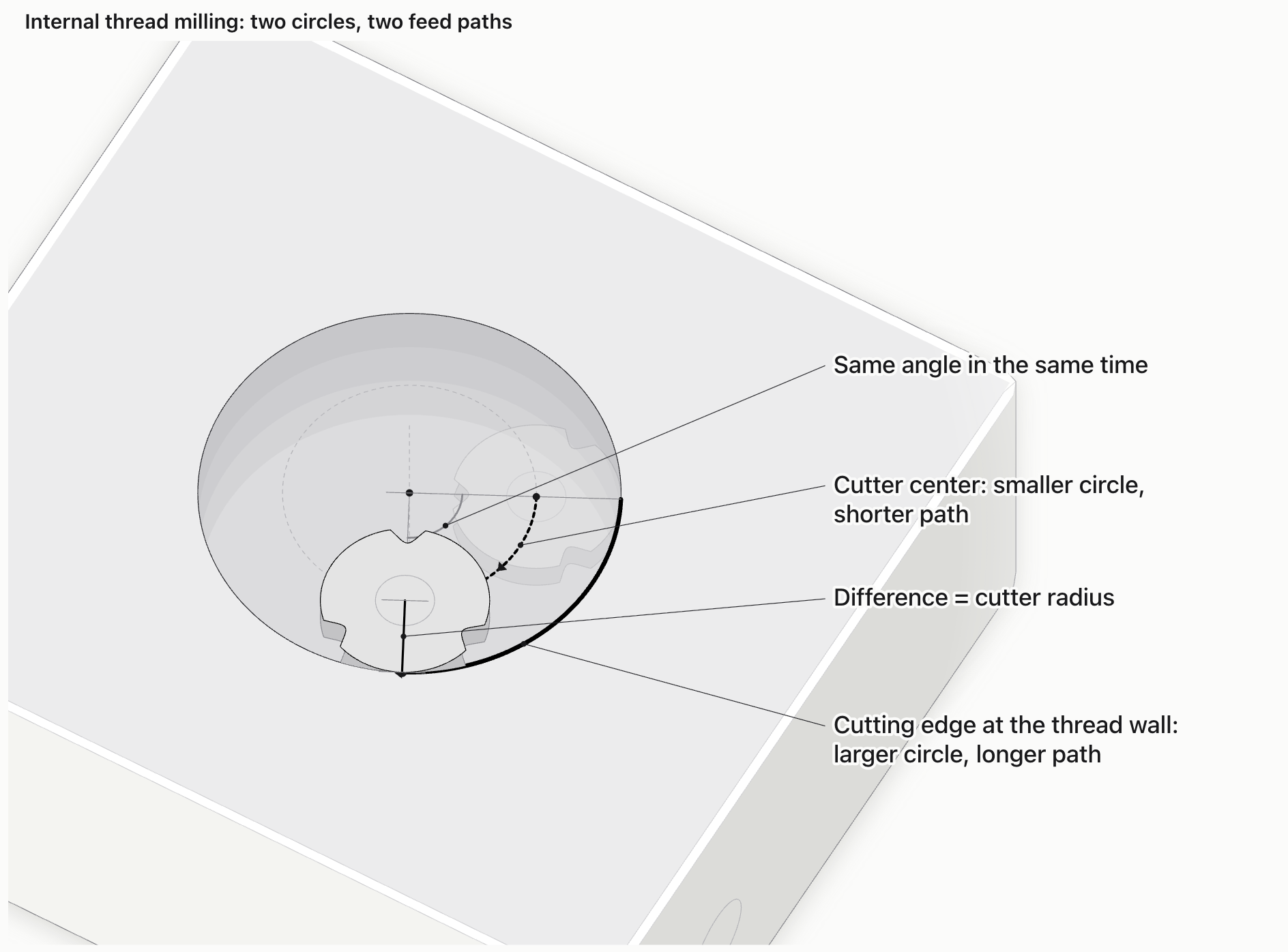
In internal thread milling, the cutter center travels a smaller circle than the cutting edge at the thread wall. Gühring's thread-milling guide separates the two feeds. If the tool supplier quotes feed at the contour and your CAM programs the center, the edge runs faster than you intended. Confirm which path each number refers to before it goes into the control.
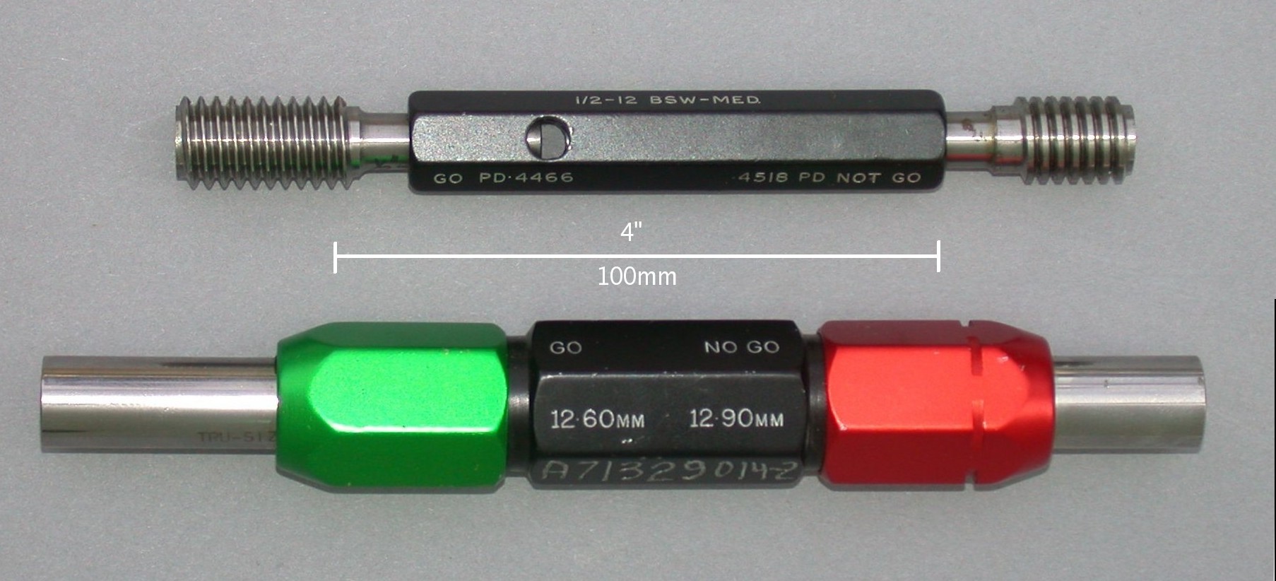
Try coolant and chip clearance in the same test cut. Radius compensation can bring the thread to size, but it can't clear a cutting zone packed with chips. Run the entry, the full-depth pass and the exit in a real hole, then check the thread with a gauge.
Choose the route your job can support
Ask these questions for each threaded hole:
- Is your current tapping process meeting thread quality and cycle time, with breakage you can live with? Keep tapping.
- Would one broken tap scrap a part worth far more than the extra cycle time? Trial thread milling.
- Do you need to adjust thread size without changing the tool? Thread milling does that through the path.
- Does your control support synchronized tapping and three-axis helical interpolation, and does your CAM post output both correctly? If not, fix that first.
- Is there little room below the last thread? Check chip evacuation for either route before you choose.
Matching the machining envelope
At Chansin CNC, we start from the part and the fixture, then set up the control, holder and coolant for threading. Our CS-T6 and CS-T7 drilling-tapping centers run rigid tapping on BT30 spindles, with XYZ travels of 600/400/300 mm and 700/500/350 mm, and can be configured with through-spindle coolant for deep holes. For larger parts, the CS-V855 in our VMC range offers 800/550/550 mm of travel.
Send us the thread drawing, material, full-thread depth and batch size through our product inquiry page. We'll check spindle torque and control functions against your holes, recommend a configuration, estimate cycle time and quote.
FAQ
What's the difference between a tap and a thread mill?
A tap cuts the whole thread as it feeds along the hole axis, one pitch per revolution. A thread mill is smaller than the hole and cuts the thread as the machine moves it along a helix around the bore. That's why tapping depends on synchronization, and thread milling on interpolation.
Can a three-axis VMC mill internal threads?
Yes, if its control supports simultaneous X, Y and Z helical interpolation. You also need a suitable cutter and a correct program. Five-axis motion isn't needed for a thread whose axis is parallel to the spindle.
Can one thread mill cut several thread diameters?
Yes, as long as the threads share the same pitch: the cutter forms the pitch, and the path sets the diameter. The smallest diameter is limited by the cutter size and the clearance it needs in the bore.
Sources and Method
- Sandvik Coromant — Thread milling: helical motion and machine requirements.
- EMUGE — Three Reasons to Thread Mill (28 January 2022): size adjustment and broken-tool consequences.
- Gühring — Thread-milling guide, PDF page 81: cutter-center and contour paths.
- OSG — FAQ 17628: simultaneous three-axis motion and same-pitch use.
- OSG — SynchroMaster: synchronized tap holder with a micro compensator for axial force in rigid tapping.
The valve-body example is illustrative. Model dimensions are Chansin CNC product data.
Feature photo: Kistler / BIG DAISHOWA.