Through-spindle coolant (TSC) makes sense when external coolant cannot reliably reach the cutting edge or carry chips out of a confined cut. Deep or blind holes, small coolant-fed drills, stringy chips and high annual hole counts are the strongest cases. Flood coolant can remain the better choice for shallow holes, open cuts, short chips and low-volume work where the nozzles have a clear path. The decision should not be based on maximum pump pressure alone. It should be based on delivered flow through the actual tool, chip control, process stability and a measured cost per acceptable hole.
This guide compares through-spindle coolant vs flood coolant as a process decision. It explains why a single depth-to-diameter rule is not enough, how pressure and flow differ, what can make a TSC system underperform, and how to calculate whether the option has a realistic payback in your shop.
What is the difference between through-spindle and flood coolant?
Flood coolant is delivered from external nozzles toward the tool and workpiece. It works well when the jet can reach the cutting zone and there is enough open space for coolant and chips to leave. Nozzle position, flow direction and obstruction by the spindle, fixture or part all affect the result.
Through-spindle coolant sends coolant through the spindle, a compatible holder and passages inside the cutting tool. The fluid exits close to the cutting edge. In drilling, it then has a second job: carrying chips back along the flutes and out of the hole.
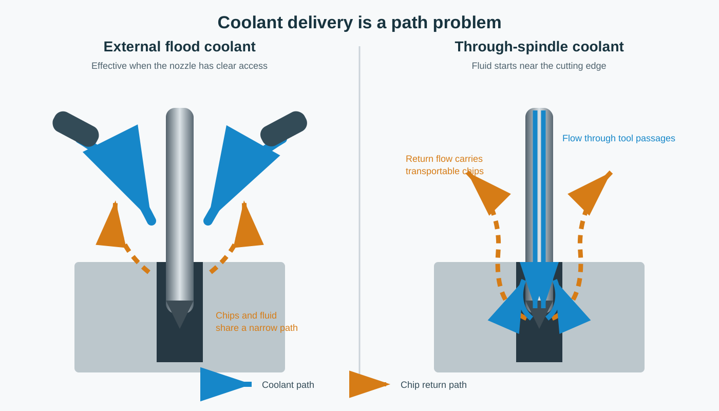
The important difference is not simply “low pressure versus high pressure.” It is where the fluid enters the cut and whether the return path can transport the chips being produced.
In drilling, chip evacuation often decides the result
At the start of a shallow hole, external coolant may reach the drill margins and flute entrances. As the drill advances, the tool body occupies most of the available space. Coolant must travel down the same narrow route that chips are trying to leave. If chips pack in the flutes, they can be recut, rub the hole wall, raise torque, damage the cutting edge or jam the drill. A related access problem appears when hidden exit burrs form inside hollow profiles, where an externally clean entrance does not reveal the condition deeper in the feature.
Coolant-through delivery changes that flow direction. Fluid arrives at the drill point and moves outward through the flutes with the chips. That does not guarantee success – the chips still need to break into a transportable shape – but it gives the process a more favorable flow path.
Seco Tools recommends coolant-through tools for drilling and, within its drilling guidance, limits external coolant to no more than 3×D for acceptable chip evacuation while reducing cutting speed relative to coolant-through operation. Guhring’s procedure for its RT 100 T deep-hole drill uses a pilot hole, starts high-pressure coolant after the tool is supported, and then allows continuous drilling without a peck cycle. These are useful examples, but they are not universal laws. They describe particular tool systems and operating conditions.
Why 3×D or 5×D is a screening rule, not a universal switch
The ratio L/D divides hole depth by drill diameter. A 40 mm deep hole made with an 8 mm drill is 5×D. The ratio is useful because a longer, narrower escape path usually makes coolant access and chip transport more difficult.
However, two holes with the same L/D can behave very differently. The result also depends on:
- whether the hole is blind or through;
- drill geometry, flute volume and coolant-channel size;
- chip length, width and stiffness;
- material tendency to form built-up edge or long chips;
- cutting speed, feed and runout;
- hole entry and exit conditions;
- coolant concentration, filtration and temperature;
- the pressure-flow performance of the complete machine-tool-holder system.
A shallow stainless-steel blind hole with poor chip breaking may be less stable than a deeper aluminum through-hole with short chips and an open exit. Use L/D to identify risk, then run a practical test based on the tool maker’s data to set the process.
Pressure and flow are not the same capability
Pressure helps overcome resistance in the pump, hoses, rotary union, holder and small passages inside the tool. Flow is the volume of coolant available to remove heat and carry chips. A pressure gauge can show a high value when a small passage restricts the flow; it does not prove that enough coolant is leaving the tool.
ISCAR’s drilling handbook expresses the relationship for a given tool as P = kQ2, where P is inlet pressure, Q is volumetric flow and k represents the hydraulic resistance of that tool. It also shows that coolant velocity depends on Q/A, where A is the passage area. The practical implication is simple: the same pump can behave very differently with two tools that have different coolant-hole sizes.
Filtration is part of this hydraulic chain. Haas service guidance identifies contamination in the auxiliary TSC filter as a frequent cause of low flow through the spindle. A machine may therefore have a healthy pump rating but poor delivery at the cutting edge because of a clogged filter, a leaking interface, a restricted holder or a partially blocked tool.
A four-question decision framework
| Question | Flood coolant is more likely to be enough | TSC is worth a shop-floor trial |
|---|---|---|
| 1. Can coolant reach the edge? | Shallow hole or open cut; nozzle has a clear, stable aim | Deep or blind feature; tool, fixture or part blocks the external jet |
| 2. Can chips escape? | Short chips leave without packing; spindle load is stable | Chips recut, pack in flutes, mark the bore or cause load spikes |
| 3. Can the system deliver? | External flow is repeatable and easy to maintain | Measured tool-outlet flow, filtration and sealed interfaces meet the tool requirement |
| 4. Does the economics work? | Low annual volume; peck time and tool loss are small | High hole count; pecking, tool failures, scrap or manual intervention are material costs |
If the first two questions point to flood coolant and the process is already stable, TSC may add cost without solving a real constraint. If access and chip evacuation repeatedly fail, TSC is a process candidate – but only if the delivery system can support the actual tools.
When should you keep flood coolant?
Keep flood coolant when the cutting zone is open, nozzle aim remains stable, chips clear without recutting, the hole depth stays within the chosen drill’s external-coolant guidance, and annual volume does not justify the additional system. Flood coolant is also simpler for mixed maintenance work and one-off parts that use many conventional tools without coolant passages.
Before adding system complexity, improve the basics: aim multiple nozzles so the tool does not block all flow, verify coolant concentration, remove packed chips from the enclosure, correct drill runout and test a geometry that produces transportable chips. If those changes make the process stable, TSC is no longer solving the dominant constraint.
Calculate payback from acceptable holes, not assumed gains
A TSC option can reduce pecking, manual chip clearing and tool interruptions, but the gain depends on the part family. Use the following model:
Break-even holes = annualized TSC cost / [(time saved per hole / 3600 × machine-hour value) + avoided tool and scrap cost per hole]
Consider an illustrative case, not a production benchmark:
- 30 drilled holes per part and 800 parts per year: 24,000 holes;
- 7 seconds saved per hole using a continuous-drilling process recommended by the tool manufacturer;
- machine-hour value: USD 75;
- avoided tool and scrap cost: USD 0.10 per hole;
- annualized TSC system, tooling and maintenance premium: USD 6,000.
The time value saved per hole is 7/3600 × 75, or about USD 0.146. Adding USD 0.10 of tool and scrap avoidance gives USD 0.246 per hole. The break-even volume is therefore about 24,400 holes per year. At 24,000 holes, the example is close to break-even; a small change in tool life, scrap, downtime or maintenance can change the decision.
Do not count on this payback until the current peck time, tool failures, scrap and expected tool-outlet performance have been estimated or measured.
When TSC can still fail
TSC does not correct every drilling problem. Common failure paths include:
- Long, unbroken chips: more coolant cannot reliably transport a chip shape that will not fit the return path.
- Insufficient outlet flow: a high gauge reading can coexist with restricted flow through a small or blocked passage.
- Poor filtration: fine passages and rotating-union components increase the importance of coolant cleanliness.
- Leaking interfaces: losses at the spindle, pull stud, holder or tool reduce useful delivery.
- Runout or weak setup: uneven cutting load, poor centering and unstable workholding are not coolant problems.
- Wrong drilling sequence: some deep-hole drills require a pilot hole and controlled entry before full speed and pressure are applied.
- Blind-hole end effects: coolant and chips need room to leave; the final approach and breakthrough strategy still require tool-specific programming.
If TSC produces unstable results, check chips, outlet flow, filter condition, leakage, runout and the tool maker’s procedure before increasing pressure.
How to verify whether a TSC system is actually working
A pump pressure label does not prove useful delivery at the cutting edge. Check the full coolant path with the actual tool under the conditions used in production:
- Confirm that the cutting tool, holder and pull-stud interfaces are compatible with coolant-through operation.
- Measure outlet flow through the smallest relevant tool passage instead of relying only on pressure at an open pump outlet.
- Check filter condition, filtration level and any clogging or differential-pressure indication.
- Inspect the spindle, rotary union, holder and tool interfaces for leakage that reduces useful flow.
- Confirm the applicable spindle-speed, coolant-type and duty-cycle limits while TSC is active.
- Run the actual drill, material, depth and cycle, then record chip form, cycle time, spindle load and hole quality.
Test the current and TSC processes under the same conditions. Compare cycle time, peck count, spindle load, chip shape, tool life, hole size, straightness, surface condition, scrap and manual intervention over enough holes to see whether any improvement is repeatable.
Frequently asked questions
Is through-spindle coolant only for deep-hole drilling?
No. It can also help in deep pockets, reaming and other operations where external access is poor. Deep-hole drilling is simply the clearest case because coolant and chips must share a restricted path.
Can flood coolant drill deeper than 3×D?
Sometimes, depending on the tool, material, hole geometry and cycle. The 3×D figure appears in specific manufacturer guidance, but it should be treated as a risk screen rather than a universal prohibition. Follow the selected drill’s data and confirm the result on the actual part and cycle.
How should you validate TSC before adopting it?
Run the actual part or a representative test using the smallest relevant coolant-through tool. Measure delivered flow and compare cycle time, chip evacuation, tool life and hole quality against the current flood-coolant process over enough holes to expose variation.
Engineering conclusion
Through-spindle coolant is most valuable when coolant access and chip transport are the real constraints. Flood coolant remains a sound choice when the cut is accessible and already stable. Start with the hole, tool, chip and annual volume; then verify pressure and flow through the actual delivery path.
A sound TSC decision combines the tool manufacturer’s recommended process, measured outlet performance, a maintained filtration system and a cost model based on acceptable holes. TSC is not a generic performance badge. It is useful only when it improves the actual cutting process.
Sources and Method
- Seco Tools, “Drilling Application” – coolant-through and external coolant guidance, including the conditions stated for external delivery.
- Guhring, “Technical Information – Deep Hole Drilling” – product-specific pilot-hole, coolant and drilling procedure for RT 100 T drills.
- ISCAR, “General Drilling Handbook” – pressure, flow, passage area and troubleshooting relationships.
- Haas Automation, “HPC-1000/TSC-1000 Auxiliary Coolant Filter Maintenance” – manufacturer service evidence linking filter contamination with reduced through-spindle flow.
The four-question selection framework and break-even model are original syntheses. The numerical example is intentionally hypothetical and should be replaced with shop-specific cycle, tooling, scrap and maintenance data.