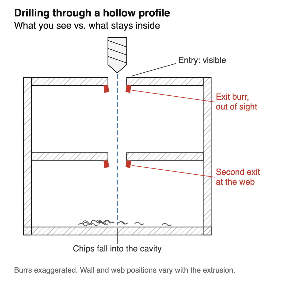
If you drill hollow aluminum profiles, you’ll know they behave differently under a drill. The thin wall gives way as the drill breaks through and pushes the burr into the cavity, where nobody can see or reach it. Whatever chips the cut makes fall in after it.
One machinist met this on a much simpler part: holes in one wall of rectangular aluminum tubing, for blind rivets. The rivet holes had to be deburred, and the back of every hole was inside the tube. He could see the entrance. He couldn’t reach the exit.
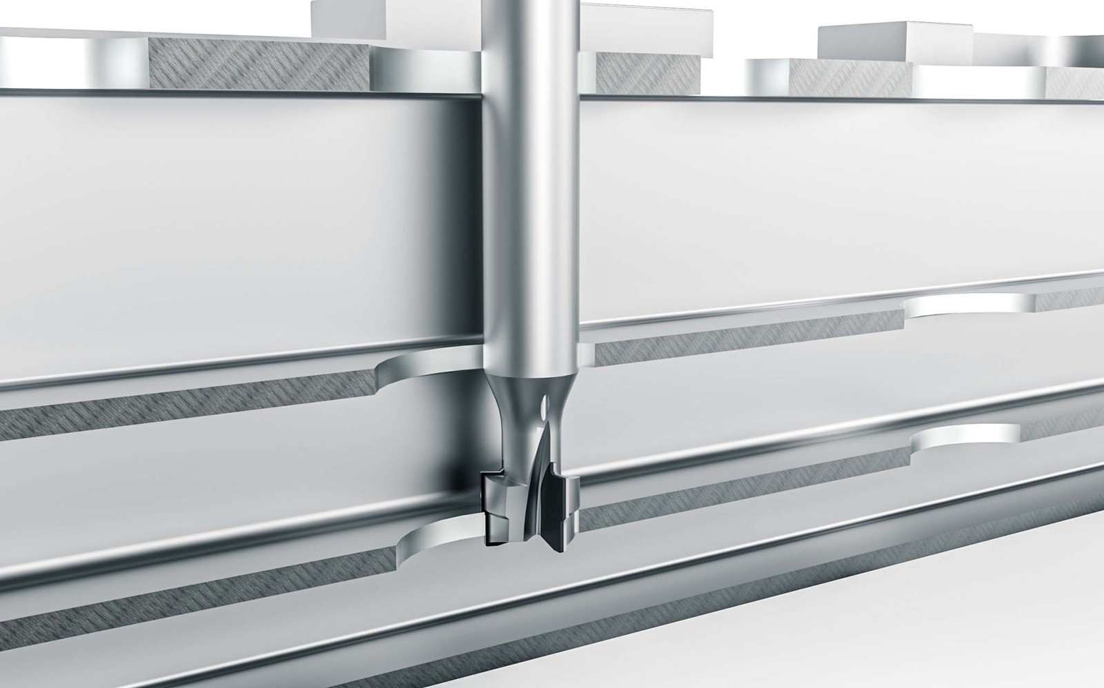
A battery tray rail is the same problem, several layers deep. Tool maker MAPAL describes battery frames as frame elements welded together after pre-machining, with bores through multiple layers, and says long drilling chips left inside the frame used to be a real process risk.
The cavity blocks access to the exit burr and holds the chips, and the thin wall limits how the hole can be tapped. Each of these asks something specific of your machine.
1. Control the breakthrough
As the drill breaks through a thin wall, there’s less and less metal ahead of it to resist the push, and the last of it bends out into the cavity as a burr. Where the cavity leaves no room for a backing support, the control has to come from the cut.
In a study on Al-5005, each hole was drilled in two stages: normal feed first, then the CNC dropped the feed to one tenth for the last part, without retracting the drill. Exit burr height fell by 35% and burr thickness by 25%, with no longer drilling time.
Your program can slow the feed before each wall breaks through, but the change point has to match where the wall really is. Measure a few of your profiles first, because walls and webs move with the extrusion.
2. Deal with the back of the hole in the same setup
If the back edge of the hole is going to be dealt with, it has to happen in the same program, because turning a long rail over to reach it costs a setup and the cavity still blocks access. Several of the forum replies pointed to tools that deburr both edges in one pass, with a spring-loaded blade that cuts on the way in and again on the way out.
For the machine, that’s one more tool run right after the drill. On a rail with several hole sizes, each size can need a drill, a deburring tool and a tap, so count the tool pockets the whole program needs before you pick the machine.
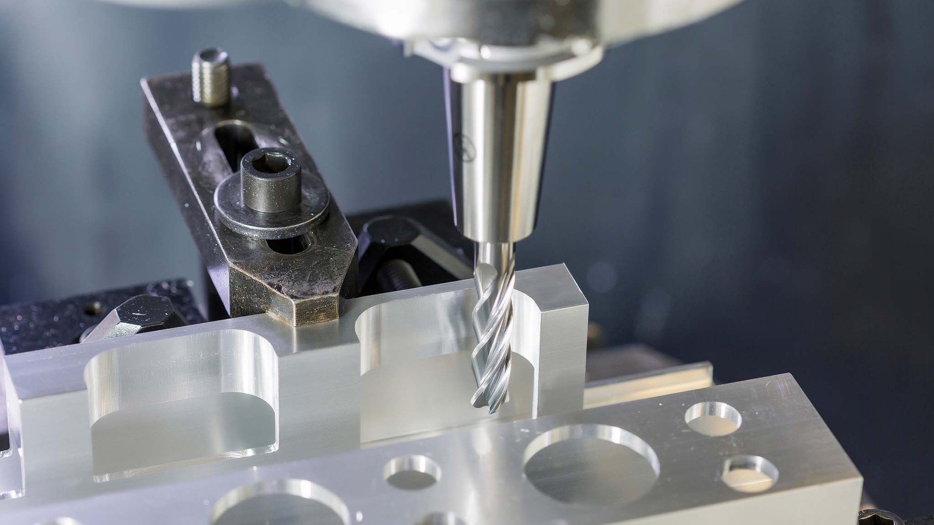
Some shops skip the drill. On MAPAL’s demonstration frame, most bores are milled with an end mill instead: the hole cycle is somewhat longer, but the chips are short and easy to clear, there are far fewer burrs, and one cutter covers several diameters. Their cutter runs at 16,000 rpm. To mill holes like this, the machine needs that speed range, smooth circular interpolation, and a tool long enough to reach the lower wall.
3. Tap thin walls with a synchronized spindle
In rigid tapping, the control locks the spindle rotation to the Z-axis feed, so the tap advances exactly one pitch per turn, through the entry and through the reversal. If the two drift apart at the reversal, the tap pulls on the threads it has just made, and a thin wall has only a few of them to give.
Forming taps are worth a look in a closed profile. They push the thread into shape instead of cutting it, so they make no chips to land in the cavity. They need an accurate pre-drilled hole and the same synchronized pitch through reversal, and on a thin wall it’s worth checking your first parts for bulging.
4. Plan the chips’ way out
Chips that leave the cut can still collect behind your internal webs. Through-spindle coolant or air pushes them out of the hole while the tool is still in it; what takes them the rest of the way is a flushing route to an open end, ideally pointed down. Plan that route while the profile is still open, because welding closes access. Our comparison of through-spindle and flood coolant covers when the pressure is worth it.
| What the profile does | What the machine needs |
|---|---|
| Bores through several layers | Interpolation and reach from one side |
| Several hole sizes per rail | Pockets for a drill, deburring tool and tap per size |
| Thin walls | Synchronized tapping through reversal |
| Closed cavities | Coolant at the cut and a flushing route to an open end |
When you don’t need any of this
When both exits of a hole are in reach and a separate deburring step fits your volume, you don’t need an automatic back-deburring cycle. And if every part carries a different hole pattern, a dedicated multi-spindle machine won’t pay for itself.
How we’d set up machines for battery tray profiles
We’ve worked with customers machining battery tray profiles. Which machine fits depends on the hole pattern.
- Mixed holes along the rail: a drill-tap center. Our T series runs a 20,000 rpm BT30 spindle with rigid tapping, on tables up to 2600 × 600 mm. For this work we’d set it up with through-spindle coolant, and a 4th axis when the holes are on more than one face. Our comparison of drill-tap centers and VMCs covers where each fits.
- The same holes on every part: a multi-spindle drilling and tapping machine. It machines several hole positions together, which suits a profile end with a repeated row of threads.
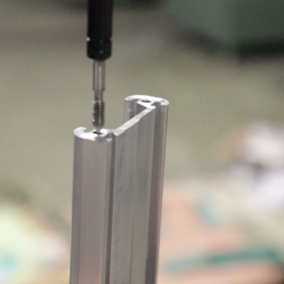
For an open profile, settle the coolant at the cut and the chips’ route to an open end before the program is written. Send us the section drawing and the hole list through our inquiry form, and we’ll suggest the machine and that setup. For machining the welded tray as a whole, see our article on EV motor housings and battery trays.
FAQ
How do you deburr the back of a hole drilled into aluminum tubing? In production, with a tool that deburrs both edges in one pass, run in the same program as the drill.
Should the holes be machined before or after the tray is welded? As much as possible before, which is how battery frames are usually built: elements pre-machined, then welded. While the profile is open, coolant has a way out; after welding, a chip behind a web may have none.
Sources
- Practical Machinist forum, De-burring the back of a blind through-hole, March 2009
- MAPAL, A strategy for battery frames, May 2023
- Erkan Bahce and Cihan Ozel, Influence of a stepped feed rate on burr formation when drilling Al-5005, Materials Testing 60(3), 2018
- HEULE, COFA deburring tool (front and back deburring in one pass)
- Sandvik Coromant, How to choose the right type of tap (forming taps)
- CHANSIN CNC T-series drill-tap center specifications and multi-spindle drilling and tapping machines
- Featured image: aluminum battery frame test part, MAPAL, cropped