
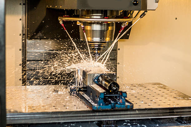
The precision of a VMC CNC metal milling machine depends on more than its advertised positioning accuracy. Machine structure, thermal deformation, cutting tools, workholding fixtures, machining parameters, and measurement methods all influence the dimensions and surface quality of finished metal parts.
For manufacturers machining aluminum, steel, stainless steel, and other engineering metals, understanding these factors helps improve production consistency and reduce scrap. It also helps purchasing teams evaluate a vertical machining center based on actual machining requirements rather than a single specification-sheet number.
This guide explains five major factors that determine CNC VMC precision, how each factor affects machining results, and what buyers should verify before selecting a machine for precision metalworking.
1. Machine Structure and Mechanical Rigidity
The mechanical structure provides the foundation for machining accuracy. Even a well-programmed CNC system cannot consistently produce precise parts if the machine deforms excessively under cutting forces or vibrates during machining.
How the Machine Structure Affects Precision
A vertical machining center typically uses a bed or base, column, spindle assembly, worktable, guideways, and drive system. These components must maintain accurate relative movement between the cutting tool and the workpiece.
Several structural factors matter:
- Bed and column rigidity: A rigid structure helps resist cutting forces and reduces unwanted displacement.
- Guideway performance: Properly designed and maintained guideways support controlled movement and stable positioning.
- Ball screw and drive system: Drive accuracy, backlash, preload, and compensation influence axis movement.
- Spindle rigidity: Spindle bearings, tool interfaces, and assembly quality affect tool positioning and cutting stability.
- Machine assembly and alignment: Geometric errors can influence squareness, straightness, flatness, and the relationship between axes.
Machine mass alone does not guarantee precision. Structural design, component quality, assembly, and the machine’s response to cutting forces must work together.
Match Rigidity to the Machining Application
Different metalworking operations place different demands on a VMC.
| Application | Main Precision Concern | What to Evaluate |
|---|---|---|
| Aluminum pocket milling | Vibration, tool deflection, and surface finish | Spindle performance, rigidity, and cutting parameters |
| Steel face milling | Cutting-force stability and dimensional consistency | Machine structure, tooling, and workholding |
| Precision hole machining | Hole position, diameter, and geometry | Spindle condition, tool runout, and measurement method |
| Mold and die machining | Contour accuracy and surface finish | Axis performance, spindle behavior, and thermal stability |
| Repeated production machining | Consistency between parts | Repeatability, fixture reliability, and process control |
The appropriate machine configuration depends on the material, workpiece size, cutting forces, tolerance requirements, and production volume.
2. Thermal Deformation and Temperature Stability
Thermal deformation is a major source of dimensional variation in precision machining. Heat generated by the spindle, motors, bearings, cutting process, and surrounding environment can change the relative positions of machine components.
Where Does Machining Heat Come From?
A VMC generates heat during normal operation. Common sources include:
- Spindle rotation and bearing friction
- Motor and drive-system operation
- Cutting friction between the tool and workpiece
- Chip formation and material removal
- Coolant temperature changes
- Variations in workshop temperature
These heat sources may cause the spindle, column, bed, or worktable to expand unevenly. As a result, the tool may no longer occupy exactly the same position relative to the workpiece as it did when the machine was cold.
How Thermal Deformation Affects Finished Parts
Thermal changes can lead to:
- Dimensional drift during long machining cycles
- Differences between the first and last parts in a production run
- Changes in hole depth or feature position
- Variation in contour accuracy
- Inconsistent results between different shifts or operating conditions
The direction and magnitude of thermal errors depend on the machine design, temperature distribution, operating time, and environmental conditions. Thermal deformation should therefore be evaluated under representative operating conditions rather than assumed from a cold-machine inspection alone.
Practical Ways to Control Thermal Errors
Stabilize operating conditions. Follow the machine manufacturer’s recommended warm-up procedure before demanding precision operations.
Manage workshop temperature. Avoid large temperature fluctuations and direct heat sources near the machine where practical.
Maintain cooling systems. Check coolant condition, flow, filtration, and temperature control according to the machine and process requirements.
Use thermal compensation when appropriate. Some CNC systems can compensate for estimated thermal errors, but the effectiveness depends on the machine design, sensors, calibration, and compensation model.
Validate accuracy during operation. For demanding applications, compare measurements taken at different operating stages to identify dimensional drift.
ISO 230 includes separate test methods for positioning accuracy and thermal effects. Buyers can use these standards as a basis for defining machine acceptance and verification procedures. ISO 230-2:2014
3. Cutting Tools, Tool Holders, and Spindle Condition
A precise machine can still produce inaccurate parts if the cutting tool is worn, incorrectly installed, or unsuitable for the material and machining operation.
Tool Wear and Cutting Performance
As a tool wears, its cutting geometry changes. This can increase cutting forces, heat, vibration, and surface irregularities.
Common consequences include:
- Oversized or undersized features
- Poor surface finish
- Increased burr formation
- Chatter marks
- Dimensional differences between successive parts
Tool life depends on the workpiece material, cutting speed, feed rate, depth of cut, coolant conditions, and tool material or coating. Buyers and production teams should establish tool-change criteria based on actual process results instead of relying on a universal tool-life estimate.
Tool Runout and Holder Quality
Tool runout refers to variation in the position of the cutting edges as the tool rotates. Excessive runout can cause some cutting edges to remove more material than others.
Potential causes include:
- Contamination on the spindle taper or tool holder
- Damaged or worn tool holders
- Incorrect clamping
- Poor tool balance at the required operating speed
- Spindle bearing or interface problems
To reduce these risks, keep mating surfaces clean, inspect holders regularly, verify runout using a suitable instrument, and follow the specified tool-clamping procedure.
Match Tooling to the Workpiece Material
| Workpiece Material | Tooling Considerations | Precision Risks |
|---|---|---|
| Aluminum | Sharp cutting edges, suitable flute geometry, effective chip evacuation | Built-up edge, chip recutting, and surface damage |
| Carbon steel | Appropriate tool grade, coating, and cutting parameters | Wear, heat, and cutting-force variation |
| Stainless steel | Heat management, suitable edge geometry, and stable engagement | Work hardening, excessive heat, and accelerated wear |
| Hardened steel | Suitable carbide or specialized tooling and controlled finishing passes | Tool deflection, edge damage, and contour errors |
Tool selection should follow the material grade and machining conditions. No single tool geometry or coating is ideal for every metal.
4. Workholding Fixtures and Workpiece Positioning
Workholding determines how securely and accurately a part is located during machining. A VMC may position its spindle accurately, yet the finished part can still be out of tolerance if the workpiece moves, deforms, or is incorrectly aligned.
Why Fixture Design Matters
A suitable fixture must locate the workpiece consistently and resist cutting forces without creating excessive deformation.
Key factors include:
Datum selection: The fixture should locate the part from the correct reference surfaces so that machined features relate properly to the engineering drawing.
Clamping force: Insufficient force can allow movement, while excessive force may distort thin walls or delicate features.
Fixture rigidity: Flexible fixtures can vibrate or deflect under cutting loads, affecting dimensions and surface finish.
Chip clearance: Chips trapped between the workpiece and locating surfaces can prevent correct seating.
Repeatable loading: A consistent loading and clamping procedure helps reduce variation between production cycles.
Choose the Right Workholding Method
Different fixtures support different machining needs.
| Workholding Method | Suitable Applications | Main Consideration |
|---|---|---|
| Machine vise | Prismatic parts and general milling | Jaw alignment and clamping deformation |
| Custom fixture | Complex shapes and repeat production | Datum accuracy and fixture stiffness |
| Soft jaws | Parts requiring profile-specific support | Jaw machining and seating consistency |
| Modular fixture | Flexible production and changing part designs | Repeatable locating and setup control |
| Vacuum fixture | Suitable thin, flat, nonporous components | Holding force and resistance to cutting loads |
The fixture must suit the part geometry, material, cutting forces, and tolerance requirements. Vacuum workholding, for example, is not appropriate for every metal part or heavy-cutting operation.
Reduce Errors During Setup
Before machining, operators should clean locating surfaces, inspect the fixture, verify the workpiece datum, and confirm that the part is seated correctly.
For tight-tolerance jobs, consider probing the workpiece to establish its actual position. Probing can reduce setup errors, but it does not replace a rigid fixture or correct datum design.
5. Measurement, Calibration, and CNC Process Control
Precision cannot be established by appearance alone. Reliable measurement is essential for confirming whether the machine and machining process meet the drawing requirements.
Understand Three Different Accuracy Concepts
Buyers should distinguish between machine positioning performance and the accuracy of the finished workpiece.
| Term | Meaning | Why It Matters |
|---|---|---|
| Positioning accuracy | How closely an axis reaches its commanded positions | Indicates the axis’s positioning performance under specified test conditions |
| Repeatability | How consistently the axis returns to a position across repeated approaches | Important for consistent production and repeated machining cycles |
| Part machining accuracy | How closely the finished part meets its specified dimensions, geometry, and tolerances | Reflects the combined result of the machine, tools, fixtures, programming, and process conditions |
A machine with good positioning repeatability does not automatically guarantee that every finished feature will meet tolerance. Tool deflection, thermal drift, workpiece movement, and measurement uncertainty can all affect the final result.
ISO 230-2:2014 specifies methods for determining the positioning accuracy and repeatability of numerically controlled machine axes through direct measurement. Its results should be interpreted according to the test conditions and parameters defined by the standard. Source: ISO
Select Appropriate Measurement Instruments
Different features require different inspection methods.
- Calipers and micrometers: Suitable for many routine dimensional checks within their capability.
- Dial indicators: Useful for checking runout, alignment, and certain setup conditions.
- Bore gauges: Useful for evaluating internal diameters when correctly set and used.
- Coordinate measuring machines (CMMs): Suitable for inspecting complex geometry and relationships between multiple features.
- Machine probes: Can support workpiece setup, tool measurement, and in-process checks when correctly configured.
Measurement uncertainty matters. Instrument resolution, calibration status, operator technique, surface condition, and temperature can all influence the reported result.
Establish a Repeatable Inspection Process
For consistent production, manufacturers should define:
- Which dimensions and geometric features are critical.
- Which measurement methods and instruments will be used.
- How often parts will be inspected.
- What acceptance limits apply.
- How measurement results will trigger corrective action.
For high-precision parts, it may also be necessary to control the measurement environment and allow the workpiece to reach a suitable temperature before inspection.
6. How CNC Programming and Cutting Parameters Influence Precision
Machine hardware is only part of the machining system. CNC programming and cutting parameters influence cutting forces, heat generation, tool engagement, and the way the tool follows the intended path.
Feed Rate, Spindle Speed, and Depth of Cut
Incorrect cutting parameters can cause excessive tool deflection, chatter, overheating, or poor surface finish.
- Spindle speed: Must suit the cutting tool, workpiece material, and operation.
- Feed rate: Influences chip load, cutting forces, and surface finish.
- Depth of cut and width of cut: Affect tool engagement and the load applied to the machine.
- Toolpath strategy: Influences how consistently the tool engages the material.
- Finishing allowance: Must leave enough material for a controlled finishing pass without creating excessive load.
A finishing pass with reduced cutting forces may improve dimensional control, but it will not correct every error caused by poor fixturing, tool runout, or machine geometry.
Control Setup and Program Errors
Incorrect work offsets, tool length compensation, cutter radius compensation, or coordinate definitions can shift the toolpath even when the machine itself is mechanically sound.
Before production, verify the program, work coordinate system, tool data, and setup sheet. Simulation and dry-run procedures can help identify programming mistakes before cutting the actual part.
For complex parts, in-process probing and tool compensation may improve consistency when the machine, control, and process support those functions.
7. How to Evaluate VMC Precision Before Purchasing
For B2B buyers, the best way to evaluate a VMC CNC metal milling machine is to match its documented performance to the intended workpiece and tolerance requirements.
A Practical Buyer Checklist
| Evaluation Area | What to Confirm |
|---|---|
| Machine structure | Structural design, spindle configuration, guideways, and intended cutting load |
| Axis performance | Positioning accuracy and repeatability, including the applicable test method |
| Thermal behavior | Warm-up guidance, thermal specifications, and compensation features if available |
| Spindle and tooling | Spindle condition, tool interface, runout requirements, and tooling compatibility |
| Workholding | Table capacity, fixture space, locating method, and clamping requirements |
| CNC control | Supported compensation, probing, tool measurement, and program verification features |
| Inspection capability | Available measurement equipment and the proposed acceptance procedure |
| Application testing | Whether the machine can demonstrate the required result on a representative part |
Request Evidence Instead of Relying on a Single Number
A specification sheet may list positioning accuracy or repeatability, but buyers should ask how these figures were measured and under what conditions.
For demanding applications, consider requesting:
- Applicable positioning test results
- Geometric inspection records
- A representative machining or acceptance test
- Defined measurement methods and acceptance limits
- Documentation of the workpiece material, tooling, and cutting conditions used in the test
A machining trial is especially useful when the part has tight tolerances, complex contours, or demanding surface-finish requirements. The trial should use agreed conditions and a documented inspection plan.
Frequently Asked Questions
1. What is the most important factor affecting VMC machining accuracy?
There is no single factor that dominates every application. Structural rigidity, thermal stability, tooling, workholding, programming, and measurement all contribute. The most important factor depends on the part geometry, material, tolerance, and machining process.
2. Does higher machine positioning accuracy guarantee more precise parts?
No. Positioning accuracy describes machine-axis performance under specified test conditions. Finished-part accuracy also depends on tool condition, workpiece location, cutting forces, temperature, programming, and inspection methods.
3. How does thermal deformation affect a CNC VMC?
Heat can cause machine components to expand or shift relative to one another. This may create dimensional drift during long production runs. Warm-up procedures, stable environmental conditions, cooling management, and appropriate compensation can help control thermal errors.
4. Can a better cutting tool improve machining precision?
A suitable, sharp, correctly installed tool can reduce runout-related variation, cutting forces, and surface defects. However, tooling cannot compensate for every structural, thermal, fixture, or programming problem.
5. How often should a VMC be calibrated?
The appropriate interval depends on machine usage, process criticality, maintenance history, environmental conditions, and applicable quality requirements. Machines used for demanding precision work may need more frequent verification or checks after maintenance, collisions, or unexplained dimensional changes.
6. What should buyers check before ordering a CNC metal milling machine?
Start with the part’s material, size, geometry, and tolerance requirements. Then compare machine travel, structural capability, spindle and tooling configuration, positioning test data, thermal behavior, workholding needs, and the supplier’s proposed acceptance procedure.
Conclusion
The precision of a VMC CNC metal milling machine results from the interaction of mechanical structure, thermal behavior, tooling, workholding, programming, and measurement. A strong machine foundation supports accurate movement, but consistent finished-part quality also requires a stable and well-controlled machining process.
For equipment buyers, the key is to evaluate documented machine performance alongside the actual production application. Define critical tolerances, request appropriate test evidence, verify the fixture and tooling strategy, and establish a repeatable inspection process before committing to a production setup.
CHANSIN can discuss your CNC machining requirements and help you identify the machine configuration and performance criteria relevant to your metalworking application. Contact CHANSIN to discuss your workpiece specifications, machining operations, and precision requirements.

