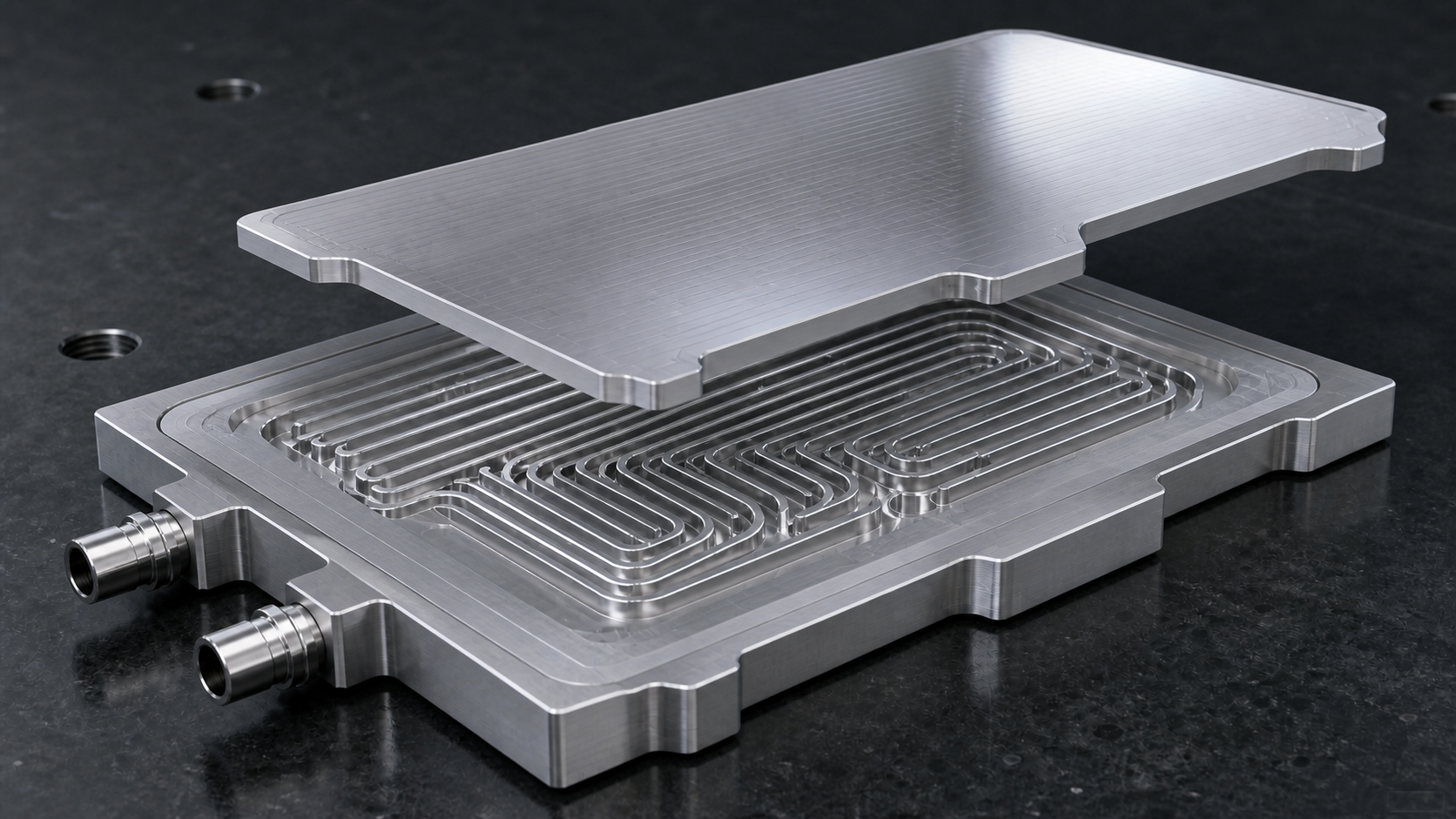
Answer first: For a two-piece metallic cold plate, the machining datum is not finished when the channels and thermal face leave the machine. Brazing, friction-stir welding or soldering can change the surface map, local stiffness and relationship between the thermal interface, ports and sealed flow path. A defensible process therefore records geometry before joining, transfers the functional datum through joining, and repeats geometry and leak verification after the thermal and pressure loads that can expose latent defects.
This article addresses one narrow question: how should joining distortion change the datum and leak-test strategy for an AI-server cold plate? It applies to joined metallic cold plates. It does not prescribe a universal flatness tolerance, leak rate, proof pressure or joining process; those values belong to the processor interface specification, coolant-loop requirements and approved product drawing.
Why a pre-join flatness result is not a release result
The Open Compute Project (OCP) describes the cold-plate heat exchanger as a base containing machined or formed channels plus a top cover, with the joint required to remain liquid-tight over service life. Its development guide lists brazing, friction-stir welding (FSW), soldering and O-ring sealing as different manufacturing routes with different trade-offs. That distinction matters: “cold plate” is a product function, not a single process.
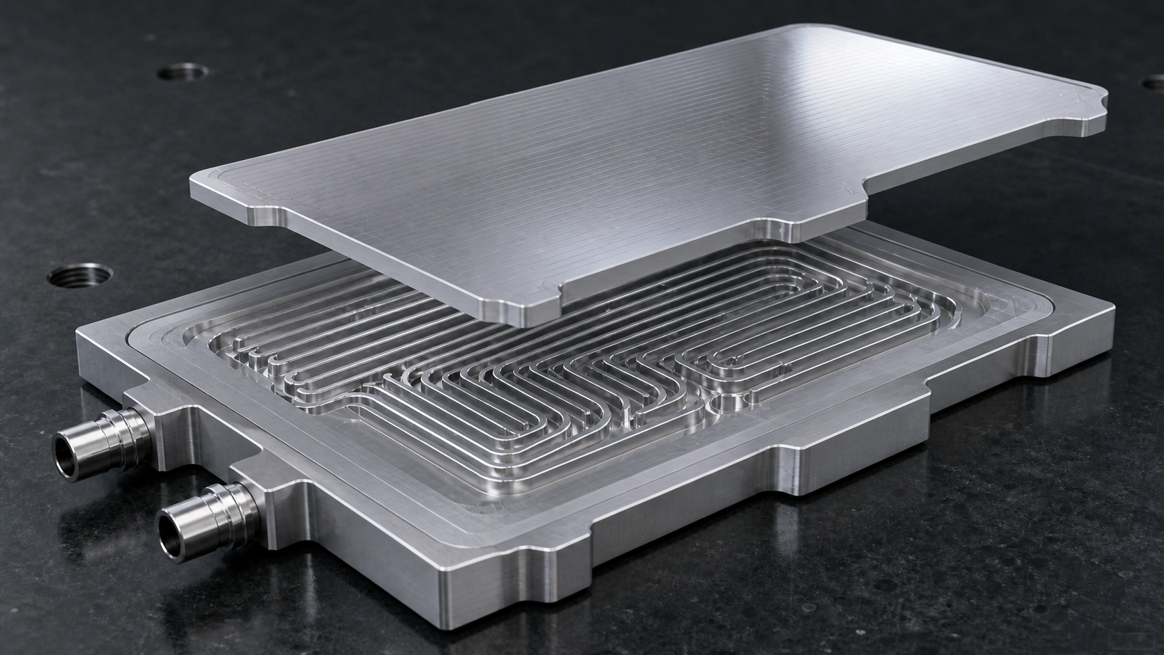
For a joined metallic design, a flat thermal face measured before joining proves only the machining state. The joining cycle can introduce heat, restraint and residual stress. Experimental work on thin aluminum FSW plates has shown that distortion magnitude and mode depend on plate geometry and process conditions; the result can be bow, twist or another spatial shape rather than a uniform offset. A maximum-minus-minimum flatness number alone can therefore hide the pattern that caused the change.
The engineering consequence is simple: the pre-join measurement is a baseline, not a substitute for post-join verification. If the drawing controls the thermal interface in the finished state, the acceptance decision must use the finished state.
Build a three-state datum model
A practical control plan separates three physical states:
| State | What is measured | What it can diagnose | What it cannot prove |
|---|---|---|---|
| M0: machined, before joining | Thermal-face surface map, channel geometry, cover and joint lands, port locations | Machining and fixturing capability | Final flatness or joint integrity |
| M1: joined, free state | The same functional features after joining and cleaning | Join-induced bow, twist, local collapse or port movement | Installed contact under retention load |
| M2: defined assembly state | Thermal interface under the specified support, fastener pattern, torque and sequence | Whether the part meets the processor-interface condition | Leak integrity unless a separate fluid test is performed |
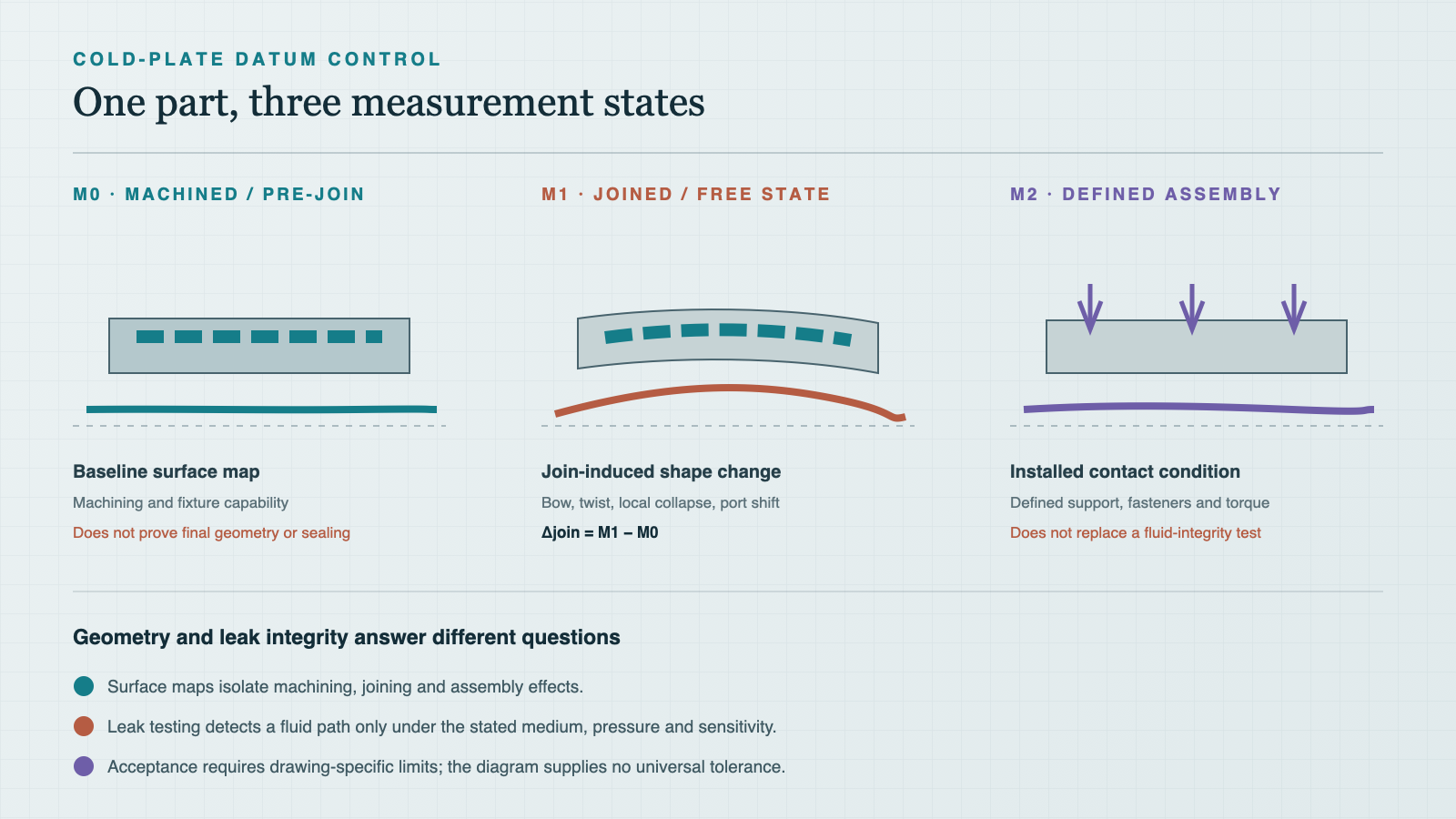
Retain the surface maps, not only the pass/fail value. Define the join-induced change as Δjoin = M1 − M0 at corresponding points. If M0 is stable but Δjoin changes by furnace batch, weld path or fixture, the evidence points to joining rather than machining. If M1 is stable but M2 changes, the retention hardware or measurement setup becomes the first suspect. This subtraction is an analysis method, not a tolerance formula.
Transfer the functional datum, not the easiest shop datum
The thermal interface is usually the most important geometric reference, but it may be inaccessible or deliberately protected during joining. The process then needs a qualified surrogate datum that survives the joining cycle. That surrogate might be a set of external pads or defined holes, but its relationship to the thermal face must be measured before joining and rechecked afterward.
A robust datum-transfer study answers four questions:
- Which feature represents the processor interface in the finished assembly?
- Which accessible features can relocate that interface after joining without forcing a distorted part flat?
- Does the join fixture constrain the part in the same way as the measurement fixture?
- Are ports, sealing lands and the thermal face evaluated in one coordinate system?
Clamping a bowed plate against a granite or fixture can produce a repeatable but misleading result. Free-state and assembled-state measurements should therefore have separate, written conditions. Neither is inherently “more correct”; each answers a different functional question.
Leak testing and geometry testing detect different failure modes
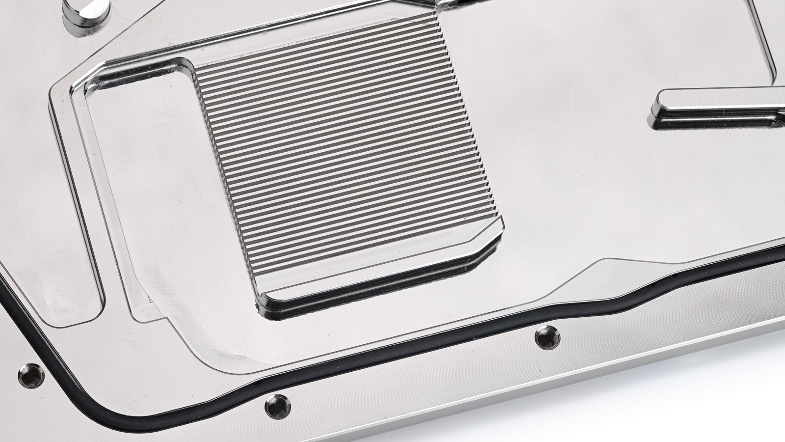
A cold plate can be geometrically acceptable and still leak through a joint void, crack, connector interface or material defect. It can also pass a leak test while the thermal face has distorted beyond its interface requirement. Leak and flatness results must remain linked by part serial number, but one must not be used as a proxy for the other.
OCP’s qualification guidance connects pressure testing with environmental exposures such as temperature cycling, shock, vibration and corrosion tests. The logic is important: a shipment leak test can detect an existing through-path, while qualification sequences challenge whether manufacturing margins remain reliable after representative stress. The exact medium, pressure, duration, temperature, sensitivity and acceptance limit must come from the approved specification; changing any of them changes what the test can detect.
| Evidence | Primary question | Typical false conclusion to avoid |
|---|---|---|
| Post-join surface map | Did the joining route change functional geometry? | “Flat means leak-tight.” |
| Production leak test | Is a detectable leak path present under this test condition? | “Pass means reliable under every service exposure.” |
| Proof-pressure test | Does the assembly withstand the specified pressure event? | “No rupture proves thermal performance.” |
| Thermal/hydraulic test | Does the flow and thermal result meet the operating requirement? | “Good thermal data identifies the manufacturing defect.” |
A worked investigation: good before joining, bad after joining
Consider a hypothetical batch in which every base passes its pre-join thermal-face requirement, but several finished plates show edge lift. A weak investigation would remachine the final face immediately. A stronger investigation preserves the evidence and compares:
- M0 maps by base and cover lot;
- M1 maps by join fixture, furnace position or weld path;
- port displacement and joint-land geometry;
- leak-test results before and after the approved proof or environmental sequence;
- material condition, joining consumables and actual cycle records.
If Δjoin clusters by fixture position while M0 does not, the join fixture or thermal field is a stronger hypothesis than the machining center. If the surface map is stable but leaks cluster after temperature cycling, joint margin or material compatibility deserves attention. If final machining restores flatness but leaves too little wall or moves the port relationship, the apparent correction can create a different risk. The decision should be made from the complete datum-and-test chain.
Engineering conclusion and limits
Joining does not merely add a cover; it creates a new geometric and fluid-integrity state. The most useful control is a correlated record of M0, M1 and—when required—M2, combined with leak and qualification evidence for the same manufacturing route. This separates machining variation from joining distortion and separates geometric acceptance from fluid integrity.
The method still requires a drawing-specific decision on the datum scheme, allowed surface shape, coolant, pressure, leak limit, joining process, retention load and environmental sequence. Without those inputs, an article can define the investigation logic but cannot declare a cold plate production-ready.
Sources and method
This article combines requirements and manufacturing guidance from the Open Compute Project cold-plate development and qualification guide and the OCP cold-plate cooling-loop requirements with peer-reviewed evidence on geometry-dependent distortion in thin aluminum FSW plates from Leitão et al., 2019. The M0/M1/M2 comparison and Δjoin diagnostic are an engineering control framework developed for this article. No universal tolerance or leak criterion has been inferred from these sources.