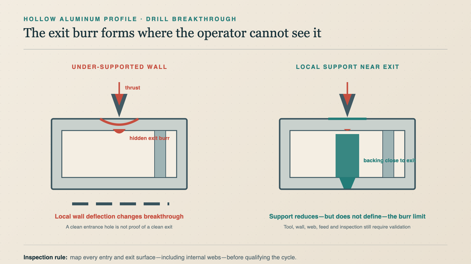
Answer first: Hidden exit burrs in hollow battery-tray profiles are not only a drill-geometry problem. Local support stiffness changes how the thin wall deflects at breakthrough, while internal webs create repeated entry and exit events that are difficult to see and deburr. The process must therefore qualify the fixture, cutting zone and inspection method as one system.
This article examines one narrow question: how does fixture stiffness change hidden exit-burr risk when drilling and tapping hollow aluminum battery-tray profiles? It does not publish a universal feed, speed, thrust limit or burr-height limit. Those depend on the profile, alloy, wall condition, tool, machine, coolant and drawing.
Why the visible hole entrance is a weak quality signal
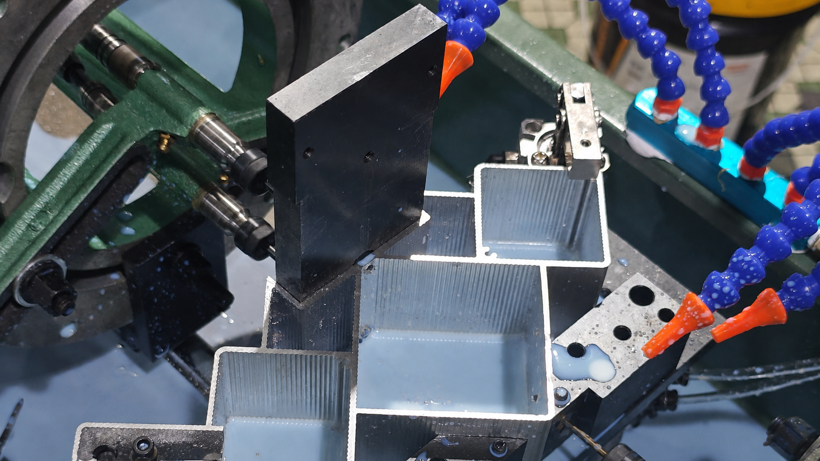
Battery-tray frames commonly use aluminum extrusions. A multi-cavity extrusion can place several walls and webs along one drilling path. The tool may enter the outer wall, break into a cavity, re-enter an internal web and break out again. Each transition changes chip support and burr formation.
An operator can see a clean external chamfer while an internal exit burr remains attached, folds into a cavity or later detaches during cleaning. That fragment can interfere with an insert, thread, joint or downstream assembly. Research on drilling and deburring multi-stage aluminum automotive frames identifies burr removal as both a quality and productivity problem; the implication is that an inspection limited to the visible entrance is incomplete.
Fixture stiffness enters the cutting equation
Near the drilling zone, a first-order model is:
δ = F / k
where δ is local deflection, F is the effective thrust acting on the wall and k is the local stiffness of the supported profile-fixture system. The equation is deliberately simple. It does not predict burr height, but it exposes the mechanism: under the same cutting force, reducing local stiffness increases displacement at breakthrough.
Consider a hypothetical comparison. If two support arrangements experience the same thrust but one has one-third of the local stiffness, the simple model predicts three times the elastic displacement. The real result will also depend on wall geometry, tool edge, dynamic response and contact conditions, but the sensitivity direction is clear. A tool change cannot compensate reliably for a support condition that moves from part to part.
Peer-reviewed work on battery-tray machining by Raffestin and colleagues reached a related conclusion at the system level: predictions of the part’s dynamic behavior and machined surface geometry were highly conditioned by how fixture stiffness and damping were modeled. Their study does not provide a universal drilling recipe, but it is direct evidence that “the machine is rigid” is not enough—the local part-fixture dynamics matter.
Locate, support and clamp are three different functions
A locator establishes position. A support reacts cutting load. A clamp keeps the part seated. Asking one thin wall to perform all three functions can deform the section before cutting begins.
| Function | Failure if poorly controlled | Validation evidence |
|---|---|---|
| Locate | Hole pattern shifts with bow, twist or section variation | Repeat loading across the approved incoming profile window |
| Support | Wall deflects at breakthrough; burr and position vary | Local displacement or dynamic-response comparison at the cutting zone |
| Clamp | Section crushes or is pulled artificially straight, then springs back | Loaded-versus-released geometry and clamp-force window |
Support should follow the moving cutting zone closely enough to maintain a qualified stiffness window, but not block chips or interfere with the tool. For a long profile with several hole stations, the support condition at the first hole may not represent the last. A fixture qualification must map the complete working length.
Map every material transition before selecting the cycle
Use the actual profile section and drill vector to list every entry, continuous-cut and exit event. Do not rely on the outside silhouette. Internal webs can move within extrusion tolerances, and a profile may have local section changes, charge-weld material or cut-end variation.
| Event | Dominant risk | Evidence to collect |
|---|---|---|
| Outer-wall entry | Walk, entry deformation or visible burr | Entry geometry and hole location |
| Outer-wall exit | Unsupported wall bends before separation | Sectioned sample or qualified internal inspection |
| Internal-web re-entry | Interrupted load, chip recutting and tool deflection | Tool-load signature and web-location study |
| Internal-web exit | Invisible burr or loose fragment | Borescope, replica, sectioning or validated cleaning/recovery test |
Computed tomography or destructive sectioning may be justified during development even when they are unsuitable for production inspection. Their purpose is to qualify a faster production signal. For example, a stable spindle-load signature may help detect a missing web or gross breakthrough change, but it cannot automatically prove burr size without a demonstrated correlation.
Thread quality starts before the tap enters
For tapped features, drill diameter, wall deflection, entry chamfer, effective material thickness, chip evacuation and tap strategy form one chain. A go/no-go result at the entrance does not reveal a damaged internal start, incomplete engagement or debris retained in a cavity.
The development study should separate at least four outcomes:
- hole location and form;
- entry and internal exit-burr condition;
- effective thread engagement and assembly performance;
- cleanliness after the defined washing and handling sequence.
Changing from a cutting tap to a forming tap, or changing drill geometry, may alter chip and burr behavior. It also changes torque, material-flow and lubrication requirements. The decision must be validated on the real alloy, wall and thread—not transferred from a solid test block.
A validation experiment that separates tool and fixture effects
A useful experiment varies one factor family at a time. First hold the tool and cutting parameters constant while comparing support locations or stiffness levels across the approved profile window. Record released hole position, internal burr evidence, load signature and thread result. Then hold the qualified fixture condition constant while comparing tool geometry or cutting strategy.
This sequence prevents a common error: selecting a tool that appears best only because it was tested in the stiffest fixture position. Include both nominal profiles and samples near the allowed bow, twist and web-location limits. The process window must cover incoming variation that production will actually accept.
Engineering conclusion and limits
Hidden exit-burr control begins with a map of the internal material transitions and a measured understanding of local support. The tool, fixture, profile and inspection method must be qualified together. A clean entrance, a machine demonstration or a single nominal section cannot prove the internal condition.
The final cutting data, support spacing, burr criterion, thread requirement and inspection frequency remain drawing-specific. The method above shows how to obtain evidence; it does not replace the development experiment.
Sources and method
The structural use of aluminum extrusions in battery trays is supported by the open-access study Mechanically Joined Extrusion Profiles for Battery Trays. Fixture sensitivity is grounded in Raffestin et al., Battery Tray Fixture Stiffness and Damping Modeling for Surface Quality Prediction. The production significance of drilling and deburring in multi-stage aluminum automotive frames is supported by Ha et al., 2023. The δ = F/k illustration, transition map and validation sequence are original engineering analysis; no source-specific cutting parameter has been generalized.