Answer first: Tool-magazine capacity should be calculated from the production window, not from the longest single program. The minimum logical count includes the deduplicated active tool assemblies, process tools, life-covering sister tools and reserve policy. The result must then be tested against physical pocket restrictions, because an oversize tool can block neighboring positions even when the nominal count appears sufficient.
This article develops one selection method: how many magazine positions are needed to run a mixed part family for a defined unattended window? It does not claim that a larger magazine is always better.
Define the scheduling boundary before counting tools
A magazine requirement has no meaning without a time and job boundary. One attended shift, an overnight run and a weekend cell can require different sister-tool coverage even when the part programs are identical. Likewise, three parts loaded simultaneously require a different union of tools from three campaigns separated by a planned reload.
State four inputs first:
- the exact part family and routing included;
- the no-reload production window;
- the planned job sequence and pallet policy;
- the allowed manual intervention and recovery policy.
Research on flexible manufacturing systems treats tool quantity, life, magazine capacity and scheduling as connected constraints. This is why “the CAM program uses 20 tools” is not a capacity study.
Normalize complete tool assemblies
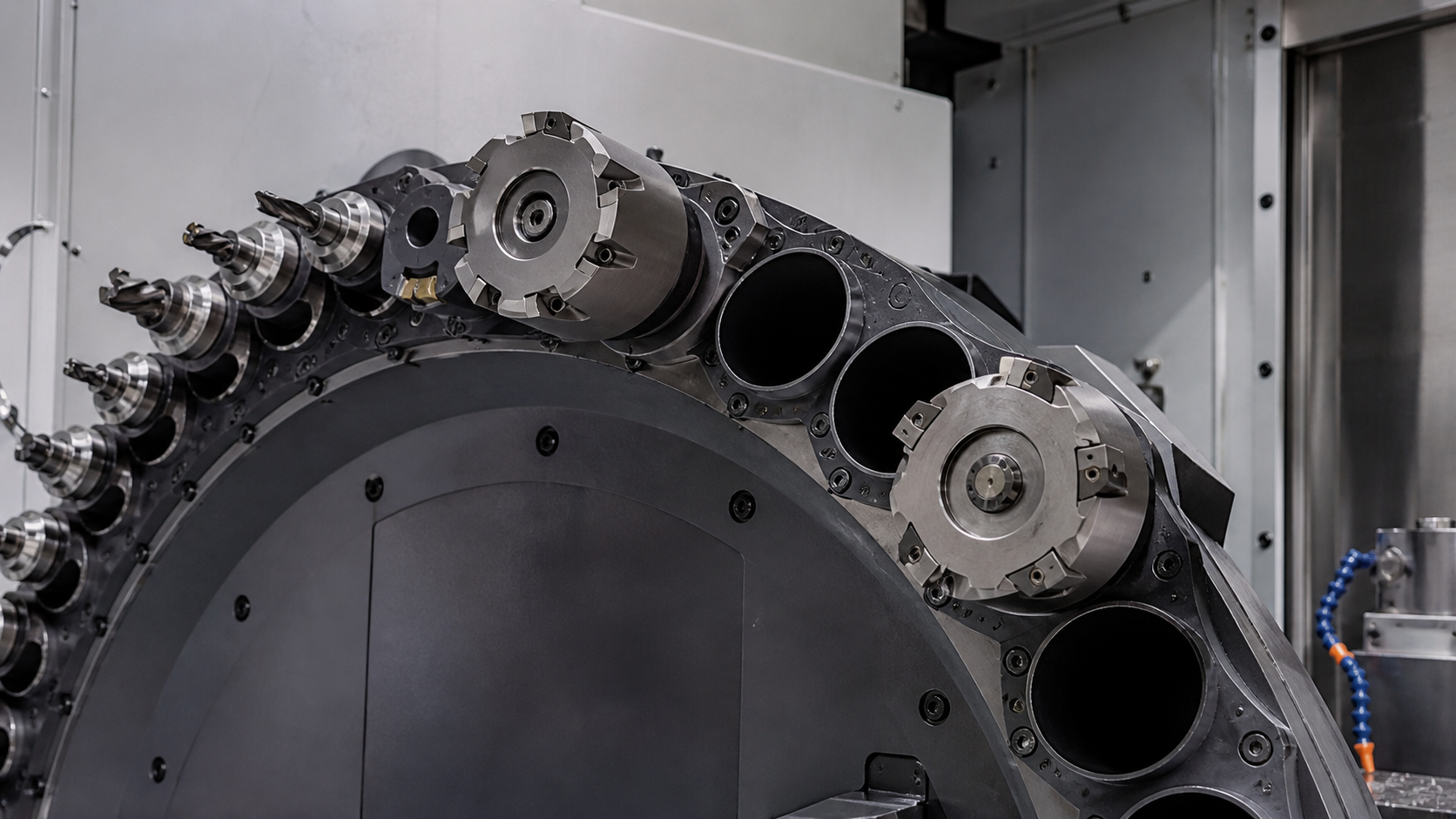
Count physical assemblies, not tool names. ISO 13399 treats cutting-tool data as structured information covering tool items, cutting items, adaptors and their relationships. In practical terms, two cutters with the same nominal diameter are not interchangeable if their holder, gauge length, insert grade, coolant delivery, balance or qualified offset range differs.
Build one row per qualified assembly with:
- stable tool ID and revision;
- cutter, insert and holder components;
- gauge length, maximum envelope and complete mass;
- spindle interface and coolant configuration;
- operations and part numbers that may share it;
- validated life unit and remaining-life rule.
Only after normalization can identical assemblies be deduplicated across programs. Deduplicating by a loose description such as “10 mm end mill” can create a false saving.
Calculate the logical requirement
For a defined production window, use:
Plogical = U + Q + S + R
where:
- U = unique qualified cutting-tool assemblies required by all jobs in the window;
- Q = process and quality tools such as probes, deburring tools or in-cycle inspection artifacts;
- S = additional sister assemblies required to cover consumption and recovery;
- R = documented reserve positions for approved recovery or engineering change.
For operation i, a first estimate of loaded assemblies is:
ni = ceil(Di / Li)
where D is expected life demand during the window and L is the validated usable life per assembly in the same unit. The additional sister count is ni − 1. Do not mix minutes, holes and cutting distance in one calculation. Include conservative recovery only where the operating policy requires it.
Worked example: three housings overnight
Consider a hypothetical unattended schedule for three related housings:
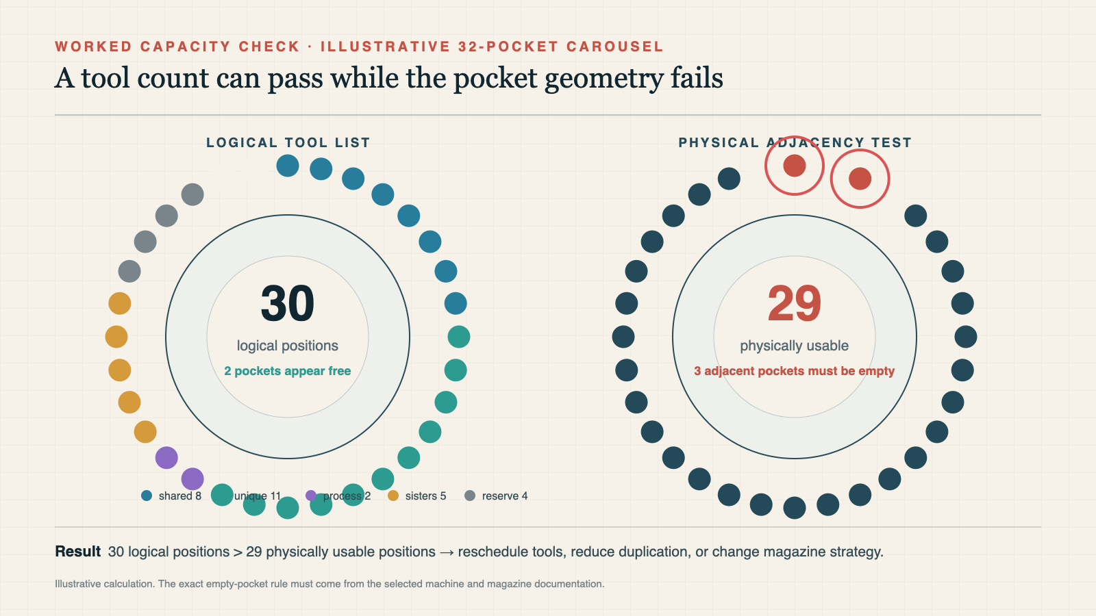
- 8 assemblies are truly shared by all three parts;
- 11 more assemblies are unique to one or two parts;
- 2 positions are used by a spindle probe and a deburring tool;
- validated life demand requires 5 additional sister assemblies;
- the written recovery policy reserves 4 positions.
The logical result is:
Plogical = 8 + 11 + 2 + 5 + 4 = 30 positions
This proves neither that a 30-pocket magazine works nor that 32 pockets provide two usable spare positions. The physical map is still missing.
Convert logical tools into a physical pocket map
For every assembly, compare maximum diameter, gauge length, mass, center-of-gravity restrictions and change path with the machine specification. If an oversize tool requires one empty neighbor on each side, it occupies one tool pocket but consumes three physical positions in that arrangement.
The interaction is not always additive. Two large tools may share one blocked neighbor if arranged appropriately, while a fixed pocket, gripper orientation or balance rule may prevent that arrangement. Create an actual circular or chain pocket map and simulate every change path; do not merely add a generic “large tool allowance.”
| Test | Failure exposed | Required action |
|---|---|---|
| Nominal count | More required assemblies than pockets | Change schedule, tooling or capacity |
| Envelope and adjacency | Blocked neighbors or tool-to-tool collision | Rearrange or reduce simultaneous tools |
| Mass and change path | Assembly exceeds changer or dynamic limit | Use an approved assembly or different process |
| Life and recovery simulation | Sisters run out before the unattended window ends | Shorten window, improve life stability or add capacity |
Use a sensitivity test before buying capacity
Recalculate at least three scenarios:
- Maximum flexibility: all three parts and all recovery tools remain loaded.
- Tool-compatible campaigns: jobs are grouped to reduce the simultaneous union, with one planned reload.
- Longer unattended operation: production demand and sister coverage increase while the part family remains unchanged.
If a controlled reload reduces the physical requirement below the available magazine with little production loss, the original problem was partly scheduling. If life variability dominates the count, process stability may be more valuable than adding pockets. If all scenarios require the same large union, more capacity has a stronger operational case.
A catalogue example: nominal capacity versus usable capacity
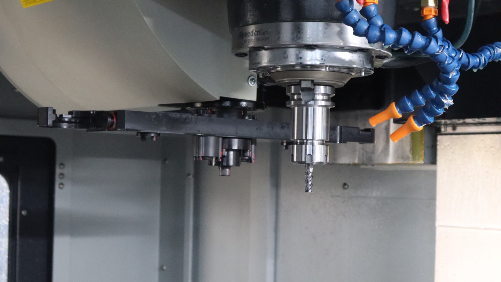
The 2026 CHANSIN catalogue provides a concrete example. The G500, G630 and G800 five-axis series are listed with 32 magazine positions, maximum tool length of 300 mm and maximum tool mass of 8 kg. The catalogue lists a maximum tool diameter of Ø70 mm with a full magazine and Ø120 mm when adjacent pockets are empty.
Return to the hypothetical 30-position calculation. If every tool fits the full-magazine Ø70 mm condition, the logical count leaves two nominal positions. If two assemblies require the Ø120 mm adjacent-empty condition, the final answer depends on their placement: the blocked neighbors can consume the apparent reserve and possibly make the 32-position arrangement infeasible. The catalogue numbers are verified product data; the 30-position schedule is only an illustration.
Magazine capacity alone cannot establish machine suitability. Work envelope, spindle interface, part and fixture mass, collision clearance, process capability and the complete current specification remain separate selection decisions.
Engineering conclusion and limits
Magazine capacity is an output of tooling, life and scheduling policy. Normalize complete assemblies, define the no-reload window, calculate sister demand, add process tools and documented reserve, then prove the physical pocket arrangement. A nominal count without that evidence can be both too small for production and unnecessarily large for the real schedule.
The method still requires validated tool life, complete assembly envelopes and the latest machine-specific magazine rules. It cannot be completed from CAM tool numbers alone.
Sources and method
The tool-data model follows ISO 13399-1. The need to integrate tool quantity, life, magazine capacity and production scheduling is supported by Zeballos, 2010 and the tool-sharing, duplicate-tool and capacity constraints studied by Avci and Akturk, 1996. CHANSIN envelope values come from the 2026 catalogue. The Plogical formula, scenario and pocket-map procedure are original engineering synthesis, not a published standard.