Answer first: A leak test can show whether a liquid-cooling manifold has a detectable pressure-boundary failure under a defined medium, pressure and test time. It cannot show that every intersecting bore is free of an attached burr, that a partly detached fragment will remain fixed during transport, or that later flow will not carry debris toward a filter, connector, heat exchanger or cold-plate channel. Flow-path cleanliness therefore needs its own evidence chain: identify every high-risk intersection, control how the tool breaks through, verify the edge condition, challenge particle release, and confirm hydraulic function separately from sealing.
This article addresses one narrow production problem: how should a manufacturer validate cross-hole deburring and cleanliness in a CDU manifold when the part already passes its leak test? It does not prescribe a universal particle limit, filter rating, flow rate, proof pressure or leak rate. Those values depend on the cooling-loop architecture, downstream restrictions, coolant, drawing and customer specification.
One part can pass one test and still fail another requirement
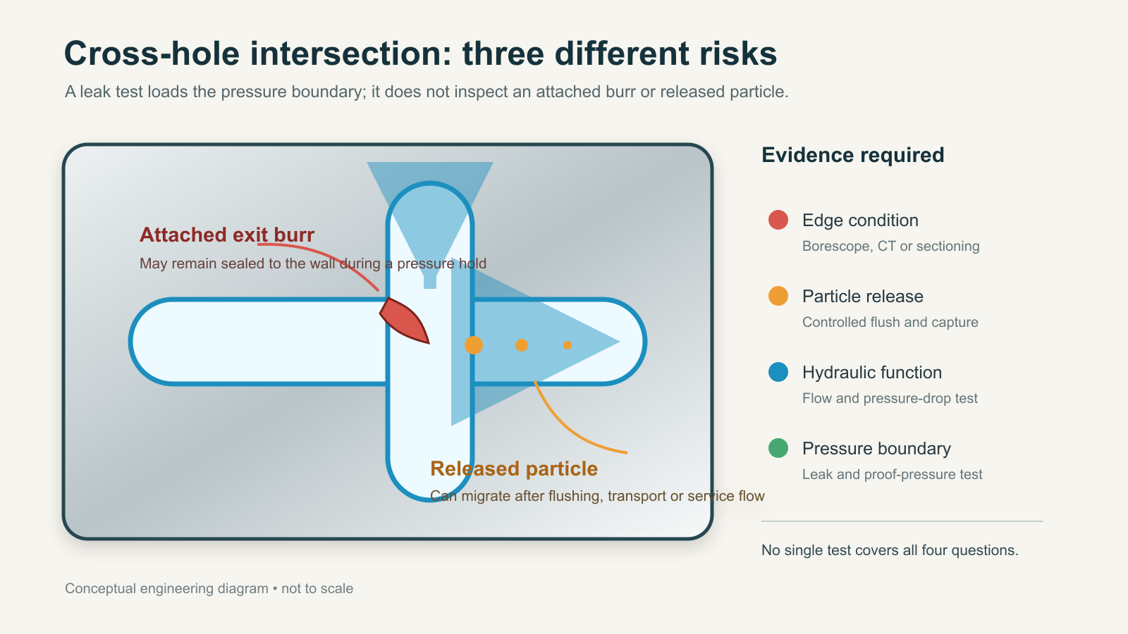
The apparent contradiction disappears when the measured objects are separated. A leak test asks whether fluid or tracer crosses the pressure boundary at a detectable rate. A burr is usually attached to a wall inside that boundary. Unless it creates a through-path or prevents a seal from seating, the leak instrument has no reason to respond. A fragment can also remain attached during the stationary test and detach later under flushing, vibration, shipping shock or repeated flow.
Open Compute Project guidance treats particulate control and leakage as related but distinct system concerns. Its cold-plate requirements discuss filtration because debris can foul narrow passages, heat-exchanger gaps and quick disconnects, reducing performance or contributing to failure. Its integration guidance also calls for manifolds and cold plates to be flushed after inspection and testing before transport. Neither statement supplies a machining tolerance; together they establish why “pressure-tight” and “clean enough for the loop” are different claims.
Why cross-hole burrs are difficult to control
At a bore intersection, the drill does not exit through a flat, uniformly supported surface. The remaining wall changes around the circumference as the cutting edge enters the existing passage. Local support falls away, and the final material may bend or tear rather than shear cleanly. The resulting edge can be uneven and hidden from the entrance of either bore.
Ohshima, Maekawa and Murata experimentally studied burrs created where a cross hole enters a main hole. Their work found that burr dimensions and deburring response depended on work material, the diameter relationship between the two holes, feed near breakthrough, drilling direction and material direction. The study also reported that a ball-burnishing method removed a smaller share of burr material on commercial aluminum than on the leaded resulfurized steel used in the same experiments. The important production lesson is not a universal percentage; it is that a method qualified on one geometry and material cannot be transferred to another by name alone.
The risk is also asymmetric. If two intersecting drills approach the same junction from different directions, they can leave different unsupported edges. A later drill may cut away part of an earlier burr, fold it into the passage, or create a new edge that cannot be reached by the original deburring tool. CAD shows the nominal intersection but not the order-dependent edge condition.
Build an intersection register before choosing a deburring process
Instead of declaring the whole manifold “deburred,” list the intersections as individual manufacturing features. For each junction, record at least:
- main-bore and branch-bore diameters and their intersection angle;
- drilling direction and operation sequence;
- the tool that breaks through into the existing passage;
- whether the far edge can be seen or physically reached;
- the direction in which flushing fluid reaches and leaves the junction;
- the nearest downstream restriction or debris-sensitive component;
- the inspection or challenge that can actually detect the expected defect.
This register changes process planning. An accessible 90-degree junction close to a large open port may be suitable for direct visual inspection and a mechanical edge-finishing tool. A deep junction behind another turn may require a different process, a sacrificial validation part, computed tomography for qualification, or a design change. The correct question is not “Which deburring technology is best?” but “Which defect at this particular edge must be removed and which method can prove that it was removed?”
A four-layer evidence model
| Evidence layer | Question answered | Useful methods | What it does not prove |
|---|---|---|---|
| Edge condition | Is an attached burr or folded lip present at the junction? | Qualified borescope view, replica, CT or destructive sectioning | That loose debris has been removed elsewhere |
| Particle release | What is released by a defined fluid challenge? | Controlled flush, membrane capture, gravimetric or particle analysis | That every attached edge is acceptable |
| Hydraulic function | Does the finished flow path meet the required pressure drop and distribution? | Flow-versus-pressure testing at defined fluid state | That future particles cannot detach |
| Pressure boundary | Is there a detectable leak or structural failure under the specified condition? | Leak and proof-pressure tests | Edge finish, particle burden or flow uniformity |
The layers should be linked by part identity and process history, not collapsed into one pass/fail label. A manifold can pass layers three and four while failing layers one or two. Conversely, a visually clean junction can still fail a hydraulic or sealing requirement.
Design a challenge that can expose a weakly attached fragment
A rinse becomes evidence only when its inputs and output measurement are controlled. “Flushed clean” is not reproducible unless the procedure defines fluid, cleanliness of the incoming fluid, direction, flow or pressure, duration, temperature, agitation or pulsing, collection method and acceptance rule. A high flow may release debris but also move it into a cavity that is not sampled. A low flow may produce a clean filter simply because it never challenged the burr.
One practical qualification strategy uses seeded or characterized defects. Create representative junctions with the production material, drill sequence and tools. Preserve a subset for CT or sectioning so the starting edge can be measured. Run the proposed deburring and flushing process, collect the discharged material, then inspect the junction again. This connects cause, release and residual edge condition. It is stronger than comparing only the final filter weight, because the same weight can come from chips, oxide, sealant, tool debris or an actual junction burr.
For a family of manifolds, qualification should cover the worst accessible and worst hidden intersections, not just the easiest port. A useful sampling rationale considers the smallest branch, largest diameter mismatch, least favorable breakthrough direction, deepest location and most sensitive downstream path. If a new drawing creates a more severe combination, it falls outside the qualified family even if the alloy and cleaning machine are unchanged.
Use process signatures to reduce destructive inspection
CT and sectioning are valuable for development but rarely economical for every production part. The route to lower inspection cost is not to remove evidence; it is to connect expensive evidence to stable process signatures. Candidate signatures include drill wear state, spindle load near breakthrough, controlled feed segment, tool-life count, deburring-tool force or pressure, flush differential pressure and captured particle trend.
The correlation must be demonstrated. For example, if borescope or CT results show that burr risk rises after a specific tool-life range, a conservative tool-change rule can be justified. If captured particle counts remain low but sectioning still finds folded lips, the flushing metric is not a sufficient proxy. Statistical stability of an easy measurement is useful only after it has been linked to the difficult-to-measure defect.
Do not let cleaning hide a machining problem
More aggressive flushing can lower the particle burden leaving the part, but it may increase cost, consume fluid, damage surfaces or merely postpone release. Likewise, chemical or electrochemical deburring can reach hidden edges, yet the process must be qualified for geometry, material compatibility, dimensional effect and waste handling. Abrasive-flow or thermal processes have their own access and damage modes. The choice should follow the intersection register and evidence model, not a universal hierarchy.
A design change can be the most robust control. Altering the bore sequence, adding a temporary access port, changing the intersection geometry or replacing a drilled network with a different manufacturing architecture may make the edge observable and controllable. That trade can reduce inspection burden, but it must be evaluated against sealing, pressure loss, packaging and production cost.
Engineering conclusion
A pressure-tight manifold is not automatically a clean manifold. The two claims fail differently and require different tests. Start with a register of every bore intersection, qualify the actual material and breakthrough geometry, challenge weakly attached debris under a controlled flush, and keep edge, particle, hydraulic and leak evidence separate. Production sampling can then move from extensive CT or sectioning toward correlated process signatures—but only after the relationship has been demonstrated.
The method does not apply unchanged to manifolds without intersecting drilled passages or to designs whose passages are fully open and inspectable before final closure. Exact cleanliness limits, filters and test conditions remain system-specific. The durable result is not one deburring recipe; it is a traceable argument that every critical intersection has a control and every control has a test capable of detecting its target failure.
Sources and Method
- Ohshima, Maekawa and Murata, “Burr Formation and Deburring in Drilling Cross Holes,” 1993 — experimental evidence on burr formation variables and ball-burnishing response.
- “Electrochemical Deburring of Cross Holes,” Journal of Materials Processing Technology — process evidence for hard-to-reach cross-hole burrs.
- Open Compute Project, ACS Liquid Cooling Cold Plate Requirements — filtration, particulate contamination and system reliability context.
- Open Compute Project, Liquid Cooling Integration and Logistics White Paper — manifold and cold-plate flushing before transport.
- Open Compute Project, Cold Plate Cooling Loop Requirements Rev. 2 — pressure and leak-test context.
The four-layer evidence model and intersection register are an engineering synthesis of these sources. They are proposed as a validation framework, not as a published standard or universal acceptance specification.